
SPN 641 FMI 7 — Turbocharger Actuator Not Responding
SPN 641 FMI 7 means the actuator is commanded but position or response is not achieved within calibrated limits. This is a combined electrical and mechanical diagnosis — sooted vanes binding the turbo mechanism are as common as actuator failure, and replacing the actuator without proving mechanical freedom produces repeat failures.
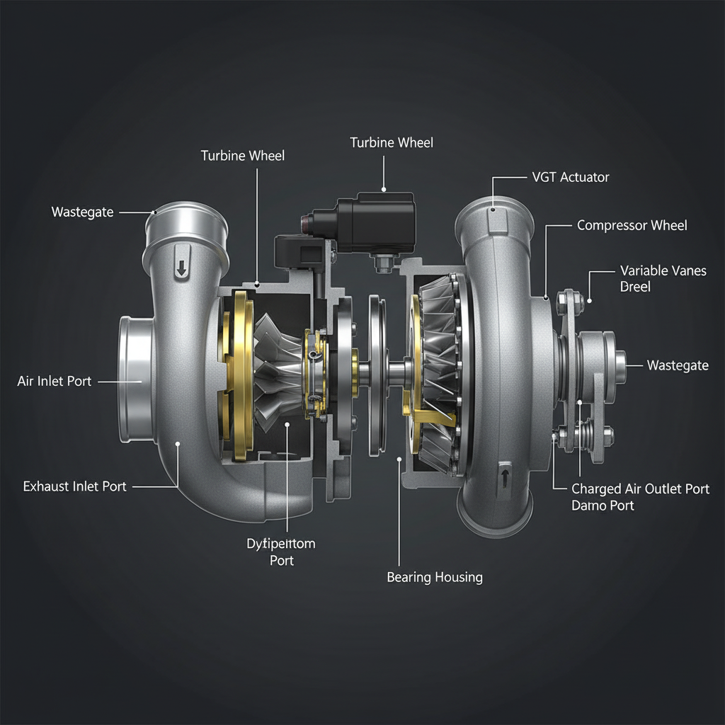
Fault Overview
FMI 7 is the not-responding or mechanical fault class. The ECM commands actuator movement and monitors the position feedback — if the actual position does not follow the desired position within calibrated time and error limits, FMI 7 sets. Sooted nozzle ring binding the VGT mechanism, failed actuator gear or motor, oil supply issues on oil-controlled designs, harness intermittents, and incorrect installation calibration are the primary causes. Replacing the actuator only, then experiencing repeat failure because the vane pack remains stuck, is the most common misdiagnosis pattern on this fault.
Engine & Platform Coverage
Symptoms
- •VGT actuator not responding fault active
- •Turbo actuator stuck indication
- •Boost not following command
- •Actuator sluggish or no movement
- •Reduced power from fixed turbo geometry
- •Increased regen frequency from underboost soot
Possible Causes
- 1.Sooted nozzle ring — carbon binding prevents vane movement
- 2.Failed actuator gear or motor — internal mechanical failure
- 3.Oil supply issues — oil-controlled actuator designs with restricted oil feed
- 4.Harness intermittents — intermittent power or ground mimicking mechanical no-response
- 5.Incorrect installation calibration — actuator not calibrated after replacement
- 6.Oil-coked mechanism — coking from extended idle or oil quality issues
Diagnostic Flow — FSM Sequence
AI Diesel Tech enforces this evidence-gate sequence. Each gate must pass before advancing.
6 steps locked behind Technician Mode- 1Single Action Gate — Desired vs Actual Position Graphing: Graph desired versus actual actuator position PIDs. If desired position changes but actual position does not follow, the actuator is not responding. If both desired and actual are stable but boost is low, the fault may be elsewhere. This PID comparison is the mandatory first step.
- 2Binary Decision Gate — Electrical Integrity Check: Verify actuator circuit power, ground, and signal integrity. Intermittent power or ground can mimic mechanical no-response. Wiggle-test the harness at operating temperature to expose intermittent connections.
- 3Override Manager — Mechanical Freedom Inspection: Inspect mechanical freedom of the turbo geometry mechanism where OEM procedure allows. This is the mandatory mechanical gate — replacing the actuator without verifying vane pack freedom produces repeat failures. Some platforms allow shaft freedom check with actuator removed.
- 4Safety Interceptor — Oil Feed Check: On oil-controlled actuator designs, verify oil feed to the actuator. A restricted oil feed prevents actuator movement regardless of electrical integrity. Verify oil pressure and flow to the actuator per OEM procedure.
- 5Resume Point — Boost Leak Test: Perform a charge air system leak test before any final turbo decision. A boost leak can produce underboost symptoms that are misattributed to actuator failure. Confirm the air path is leak-free before turbo replacement.
- 6Verification Loop — Post-Repair Position Response: After repair, verify desired versus actual position tracks correctly. Confirm boost meets setpoint under load. Verify actuator calibration if required by OEM procedure after replacement.
- 7Repair Ledger Output — Actuator vs Turbo Assembly Decision: Replace actuator after electrical proof and mechanical freedom confirmation. Replace turbo cartridge or assembly only when geometry is confirmed seized and cannot be freed by approved service procedures.
Unlock the full evidence-gated diagnostic sequence, DVOM test steps, and repair procedures in Technician Mode.
Repair Steps
4 steps locked- 1Repair harness intermittents found by wiggle testing.
- 2Service or clean turbo geometry mechanism if approved by OEM procedure.
- 3Repair oil feed restriction on oil-controlled actuator designs.
- 4Replace actuator after electrical proof and mechanical freedom confirmation.
- 5Replace turbo assembly when geometry is confirmed seized beyond service limits.
- 6Calibrate replacement actuator per OEM procedure.
Unlock full diagnostic steps, DVOM tests, and repair procedures.
Full Diagnostic Access
Verification steps, preventative measures, severity guidance, and legacy comparison are available in Technician Mode.
Start Diagnosing This Fault Now
AI Diesel Tech walks you through every evidence gate in the correct order. Choose the plan that fits your shop.
Related Resources
Related Fault Codes
Related Systems
Related Fault Codes
Related Sensor Locations
Common Symptoms
Related Articles
AI Diesel Tech — The Technician's Diagnostic Engine
AI Diesel Tech diagnostic logic is built by an ASE Certified Diesel Technician and engineered for professional shop use. Trusted by technicians nationwide — used in shops, fleets, and training programs.
Summary
SPN 641 FMI 7 is frequently mechanical binding plus electrical confirmation. The AI Diesel Tech FSM enforces the mechanical freedom gate before actuator-only closeout to prevent the most common repeat-failure pattern on VGT systems.