
DPF Inlet / Outlet Temperature Sensor Rationality During Regen
DPF temperature sensor rationality must be verified during an actual regeneration when temperatures are rising and falling rapidly.
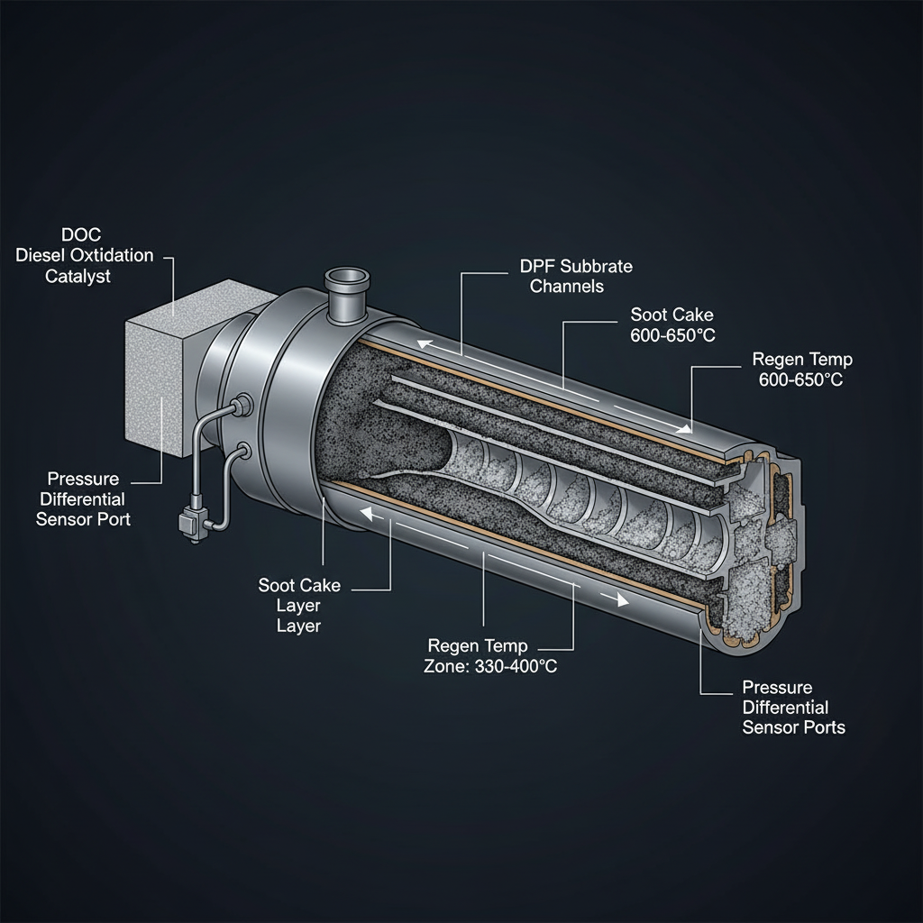
Fault Overview
Rationality faults on DPF inlet or outlet temperature sensors that appear or are critical during regeneration when temperatures are changing rapidly. Sensors often fail or become intermittent under the high temperatures of regen — a sensor that works at idle may fail rationality once the DPF is hot.
Engine & Platform Coverage
Symptoms
- •DPF temp sensor rationality
- •DPF inlet temp during regen
- •DPF outlet temp fault
- •Regen temperature sensor code
Possible Causes
- 1.Failed sensor
- 2.Wiring open/short
- 3.Exhaust leak at the sensor boss
- 4.Thermal shock damage
- 5.Incorrect sensor
- 6.Software threshold sensitivity during fast temperature rise
Wiring & Circuit Notes
Inspect connectors for heat damage and corrosion. Check harness routing near the DPF can for chafing or melting.
DVOM Specs & Sensor Tests
Resistance or voltage vs temperature chart. Correlation between DPF inlet and outlet during a controlled regen. Rate of change should be physically plausible. Infrared verification when accessible.
Diagnostic Flow — FSM Sequence
AI Diesel Tech enforces this evidence-gate sequence. Each gate must pass before advancing.
5 steps locked behind Technician Mode- 1Step 1 — Monitor DPF Inlet and Outlet Temperatures Throughout a Forced Regen: Monitor DPF inlet and outlet temperatures throughout a forced regen. Sensors often fail or become intermittent under the high temperatures of regen.
- 2Step 2 — Look for Sudden Dropouts, Spikes, or Impossible Deltas: Look for sudden dropouts, spikes, or impossible deltas between inlet and outlet. These indicate electrical intermittents that only appear under heat.
- 3Step 3 — Measure Sensor Resistance at Ambient and After a Heat Cycle: Measure sensor resistance at ambient and after a heat cycle if safe. Resistance may be unstable when the sensor is heated.
- 4Step 4 — Inspect for Leaks at the Bosses: Inspect for leaks at the sensor bosses. Leaks cause turbulent flow and can produce erratic temperature readings.
- 5Step 5 — Check Wiring Under Heat and Vibration: Check wiring under heat and vibration. Inspect harness routing near the DPF can for chafing or melting.
- 6Step 6 — Replace the Sensor That Fails Correlation or Resistance After Proof: Replace the sensor that fails correlation or resistance after proof. Do not replace both sensors without isolating the faulty one.
Unlock the full evidence-gated diagnostic sequence, DVOM test steps, and repair procedures in Technician Mode.
Full Diagnostic Access
Verification steps, preventative measures, severity guidance, and legacy comparison are available in Technician Mode.
Typical Repair Costs
Replace failed temperature sensor $120–400; repair wiring or connector $100–300; repair boss leak $50–200.
Start Diagnosing This Fault Now
AI Diesel Tech walks you through every evidence gate in the correct order. Choose the plan that fits your shop.
Related Systems
Related Fault Codes
Related Sensor Locations
Common Symptoms
AI Diesel Tech — The Technician's Diagnostic Engine
AI Diesel Tech diagnostic logic is built by an ASE Certified Diesel Technician and engineered for professional shop use. Trusted by technicians nationwide — used in shops, fleets, and training programs.
Summary
Use the AI Diesel Tech diagnostic engine to run this code through a structured, evidence-gated sequence and get a confirmed root cause before any parts are replaced.