
SCR Inlet Temperature Performance High / Low / Rationality
SCR inlet temperature performance faults require a full temperature map and exhaust leak check before sensor replacement.
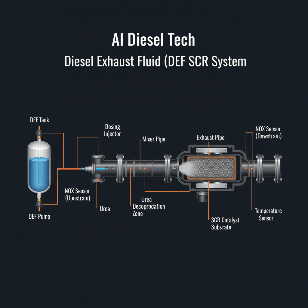
Fault Overview
Performance or rationality faults on the SCR inlet temperature sensor where the reading is implausibly high or low relative to DOC outlet, DPF outlet, or engine operating conditions.
Engine & Platform Coverage
Symptoms
- •SCR inlet temp high
- •SCR inlet temp low
- •SCR inlet temperature rationality
- •SCR inlet sensor performance
Possible Causes
- 1.Failed sensor
- 2.Wiring open/short
- 3.Exhaust leak between DPF and SCR
- 4.DOC/DPF restriction altering temperature profile
- 5.Sensor installed in wrong location or with incorrect thermal contact
- 6.Software threshold issues
Wiring & Circuit Notes
Inspect SCR inlet sensor connector and harness for heat damage, corrosion, and routing problems near the exhaust.
DVOM Specs & Sensor Tests
Resistance or voltage vs temperature chart. Correlation with DPF outlet temperature under steady flow. Infrared verification at the boss when accessible.
Diagnostic Flow — FSM Sequence
AI Diesel Tech enforces this evidence-gate sequence. Each gate must pass before advancing.
5 steps locked behind Technician Mode- 1Step 1 — Capture Simultaneous Temperature Map Under Load: Capture simultaneous DOC outlet, DPF outlet, SCR inlet, and intermediate temperatures under load. Exhaust leaks between the DPF and SCR inlet are a classic cause of rationality codes.
- 2Step 2 — Look for Large Unexplained Drops or Rises Between DPF Outlet and SCR Inlet: Look for large unexplained drops or rises between DPF outlet and SCR inlet. A large drop confirms a leak or restriction between the two sensors.
- 3Step 3 — Inspect the Exhaust Pipe and Clamps for Leaks: Inspect the exhaust pipe and clamps between the DPF and SCR for leaks. Even small leaks cool the gas stream enough to set rationality codes.
- 4Step 4 — Measure Sensor Resistance/Voltage Against Chart: Measure sensor resistance/voltage against the OEM temperature chart. Sensor drift after high-heat events is also common.
- 5Step 5 — Verify Wiring Integrity: Verify wiring integrity. Inspect SCR inlet sensor connector and harness for heat damage, corrosion, and routing problems near the exhaust.
- 6Step 6 — Replace Sensor Only After Leak and Correlation Proof: Replace sensor only after leak and correlation proof.
Unlock the full evidence-gated diagnostic sequence, DVOM test steps, and repair procedures in Technician Mode.
Full Diagnostic Access
Verification steps, preventative measures, severity guidance, and legacy comparison are available in Technician Mode.
Typical Repair Costs
Repair exhaust leak $100–400; repair wiring $100–300; replace failed sensor $120–500.
Start Diagnosing This Fault Now
AI Diesel Tech walks you through every evidence gate in the correct order. Choose the plan that fits your shop.
Related Systems
Related Fault Codes
Related Sensor Locations
Common Symptoms
Related Articles
AI Diesel Tech — The Technician's Diagnostic Engine
AI Diesel Tech diagnostic logic is built by an ASE Certified Diesel Technician and engineered for professional shop use. Trusted by technicians nationwide — used in shops, fleets, and training programs.
Summary
Use the AI Diesel Tech diagnostic engine to run this code through a structured, evidence-gated sequence and get a confirmed root cause before any parts are replaced.