
P2563 — Turbocharger Boost Control Position Sensor Circuit Range/Performance
P2563 indicates the VGT or boost control position sensor signal is out of expected range or does not correlate with commanded position. Sweep data plus learn-status verification prevent unnecessary actuator replacement. Many VGT actuators have the position sensor built in — replacement is the actuator assembly.
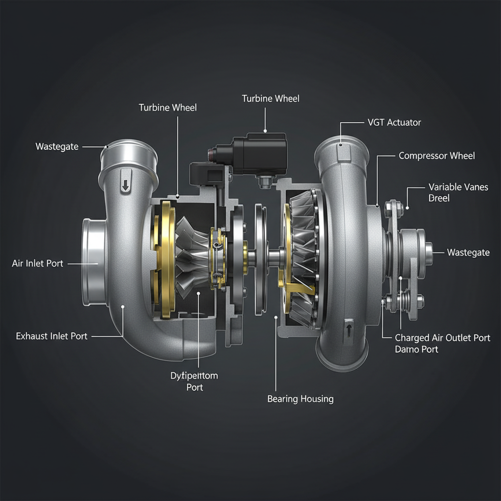
Fault Overview
Failed position sensor (often integral to actuator), wiring issues, mechanical binding causing apparent position error, poor learn/calibration, and oil intrusion into the connector are the primary causes. Oil in the connector is a frequent cause of intermittent P2563. Always attempt the learn procedure after replacement.
Engine & Platform Coverage
Symptoms
- •P2563
- •VGT position sensor performance
- •boost control position
- •turbo actuator position fault
Possible Causes
- 1.Failed position sensor (often integral to actuator)
- 2.Wiring issues
- 3.Mechanical binding causing apparent position error
- 4.Poor learn/calibration
- 5.Oil intrusion into connector
Wiring & Circuit Notes
Actuator connector, position signal, power, and ground. Check for oil contamination.
DVOM Specs & Sensor Tests
Commanded vs actual position during sweep. Signal voltage range. Learn status.
Diagnostic Flow — FSM Sequence
AI Diesel Tech enforces this evidence-gate sequence. Each gate must pass before advancing.
5 steps locked behind Technician Mode- 1Step 1 — Perform VGT Sweep and Record Position Error: Perform a VGT sweep command and record the position error between commanded and actual position throughout the range.
- 2Step 2 — Check Connector for Oil or Damage: Check the actuator connector for oil intrusion, corrosion, or damaged pins. Oil contamination is a frequent cause of intermittent P2563.
- 3Step 3 — Measure Signal Voltage Through the Range: Measure signal voltage through the full commanded range. Verify it tracks smoothly without dropouts.
- 4Step 4 — Verify Power and Ground Under Load: Verify actuator power and ground under load.
- 5Step 5 — Attempt Learn/Calibration: Attempt the VGT learn or calibration procedure. A failed learn confirms mechanical or sensor issues.
- 6Step 6 — Replace Actuator if Sensor or Motor Is Failed: Replace the VGT actuator assembly if the sensor or motor is confirmed failed. Perform the learn procedure after installation.
Unlock the full evidence-gated diagnostic sequence, DVOM test steps, and repair procedures in Technician Mode.
Full Diagnostic Access
Verification steps, preventative measures, severity guidance, and legacy comparison are available in Technician Mode.
Typical Repair Costs
Clean connector $20–80; repair wiring $80–250; replace VGT actuator and perform learn $300–1,800.
Start Diagnosing This Fault Now
AI Diesel Tech walks you through every evidence gate in the correct order. Choose the plan that fits your shop.
Related Systems
Related Fault Codes
Related Sensor Locations
Common Symptoms
Related Articles
AI Diesel Tech — The Technician's Diagnostic Engine
AI Diesel Tech diagnostic logic is built by an ASE Certified Diesel Technician and engineered for professional shop use. Trusted by technicians nationwide — used in shops, fleets, and training programs.
Summary
Use the AI Diesel Tech diagnostic engine to run this code through a structured, evidence-gated sequence and get a confirmed root cause before any parts are replaced.