
NOx Sensor Bias Effects on DEF Dosing Quantity Control
NOx sensor bias is considered only after DEF pressure, quantity collection, and circuits have been proven good.
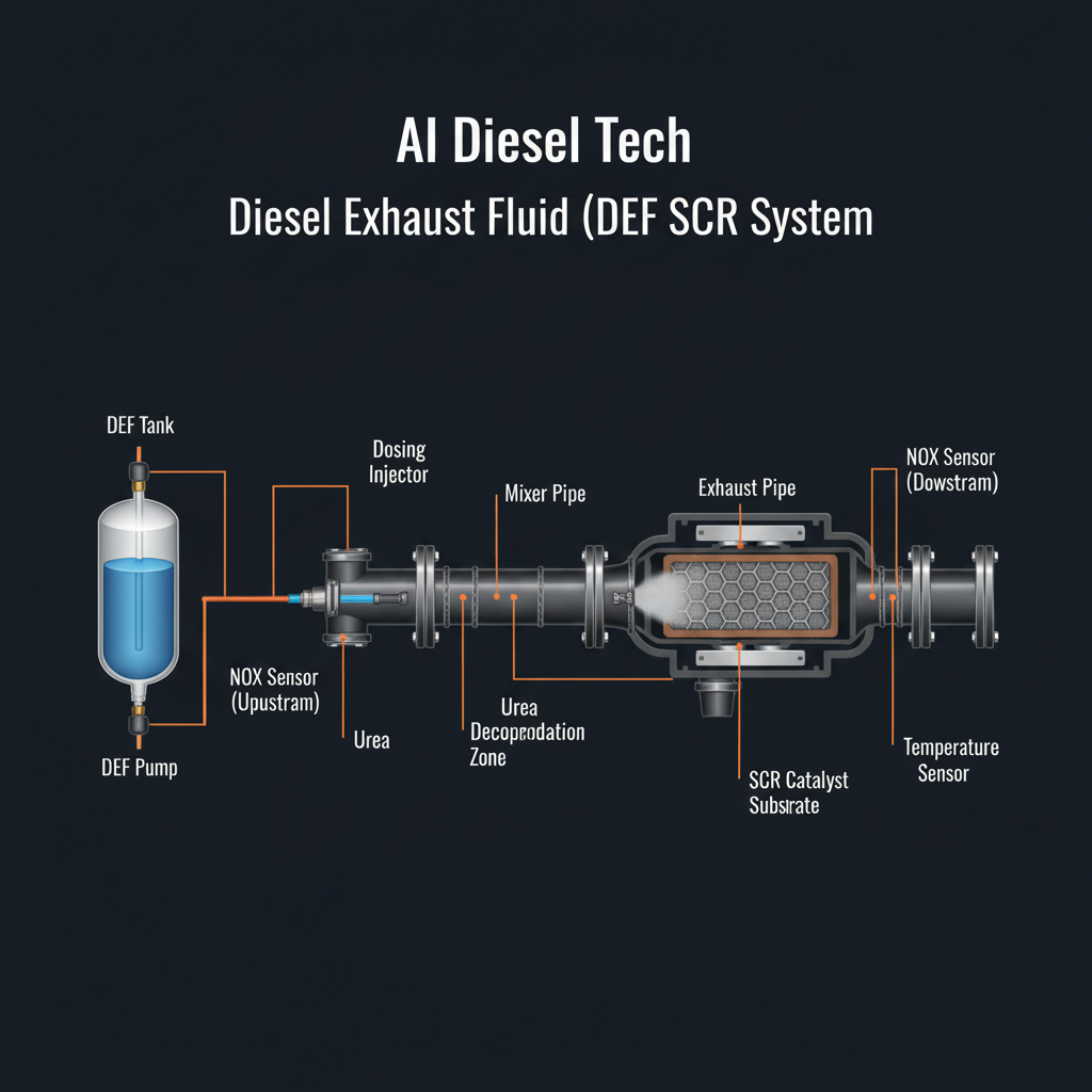
Fault Overview
Diagnosis of upstream or downstream NOx sensor bias or rationality faults that cause the ECM to command incorrect DEF dosing quantity (too high or too low) in closed-loop SCR control.
Engine & Platform Coverage
Symptoms
- •NOx sensor bias dosing
- •Incorrect DEF quantity NOx
- •SCR closed loop dosing
- •NOx rationality quantity
- •Over/under dose from NOx
Possible Causes
- 1.Aged or contaminated NOx sensors
- 2.Heater faults on NOx sensors
- 3.Wiring issues
- 4.Exhaust leaks before the sensors
- 5.Actual SCR catalyst degradation misread as sensor bias
Wiring & Circuit Notes
Inspect NOx sensor connectors and heater circuits. Check for exhaust leaks upstream of the sensors.
DVOM Specs & Sensor Tests
Compare upstream and downstream NOx values under steady conditions. Heater resistance and current. Signal rationality against expected engine-out NOx. Dosing quantity response to sensor values.
Diagnostic Flow — FSM Sequence
AI Diesel Tech enforces this evidence-gate sequence. Each gate must pass before advancing.
6 steps locked behind Technician Mode- 1Step 1 — Confirm DEF Pressure, Quantity Collection, and Circuits are Within Specification: Confirm DEF pressure, quantity collection, and circuits are within specification. NOx sensor bias is a common hidden cause of persistent quantity or efficiency codes after the DEF hydraulic system has been proven good.
- 2Step 2 — Monitor Upstream and Downstream NOx During Steady Cruise or Test: Monitor upstream and downstream NOx during steady cruise or test. Compare values against expected engine-out NOx for the operating condition.
- 3Step 3 — Check NOx Sensor Heater Operation and Circuits: Check NOx sensor heater operation and circuits. Heater faults cause sensor inaccuracy and can bias closed-loop quantity control.
- 4Step 4 — Inspect for Exhaust Leaks Before the Sensors: Inspect for exhaust leaks before the sensors. Exhaust leaks dilute the sample and produce artificially low NOx readings, causing the ECM to over-command quantity.
- 5Step 5 — Evaluate Sensor Aging or Offset Data if Available: Evaluate sensor aging or offset data if available via OEM software.
- 6Step 6 — Replace Biased NOx Sensor Only After Hydraulic DEF System is Proven: Replace biased NOx sensor only after hydraulic DEF system is proven. Prevents sensor replacement when the doser or pressure is the real fault.
- 7Step 7 — Retest Dosing Quantity and Efficiency: Retest dosing quantity and efficiency after sensor replacement to confirm the bias is resolved.
Unlock the full evidence-gated diagnostic sequence, DVOM test steps, and repair procedures in Technician Mode.
Full Diagnostic Access
Verification steps, preventative measures, severity guidance, and legacy comparison are available in Technician Mode.
Typical Repair Costs
Replace biased NOx sensor $300–700 each; repair exhaust leaks $100–400; address heater circuits $100–300. Total $300–900 per sensor.
Start Diagnosing This Fault Now
AI Diesel Tech walks you through every evidence gate in the correct order. Choose the plan that fits your shop.
Related Systems
Related Fault Codes
Related Sensor Locations
Common Symptoms
Related Articles
AI Diesel Tech — The Technician's Diagnostic Engine
AI Diesel Tech diagnostic logic is built by an ASE Certified Diesel Technician and engineered for professional shop use. Trusted by technicians nationwide — used in shops, fleets, and training programs.
Summary
Use the AI Diesel Tech diagnostic engine to run this code through a structured, evidence-gated sequence and get a confirmed root cause before any parts are replaced.