
Detroit DD13 NOx Sensor Cascade Fault Pattern
The Detroit DD13 produces a characteristic NOx sensor cascade where upstream and downstream sensor faults appear together. Upstream NOx sensor failure triggering downstream efficiency faults and both sensors failing simultaneously from shared harness issues are the most documented DD13 NOx cascade patterns. The FSM enforces upstream-first isolation before downstream sensor replacement.
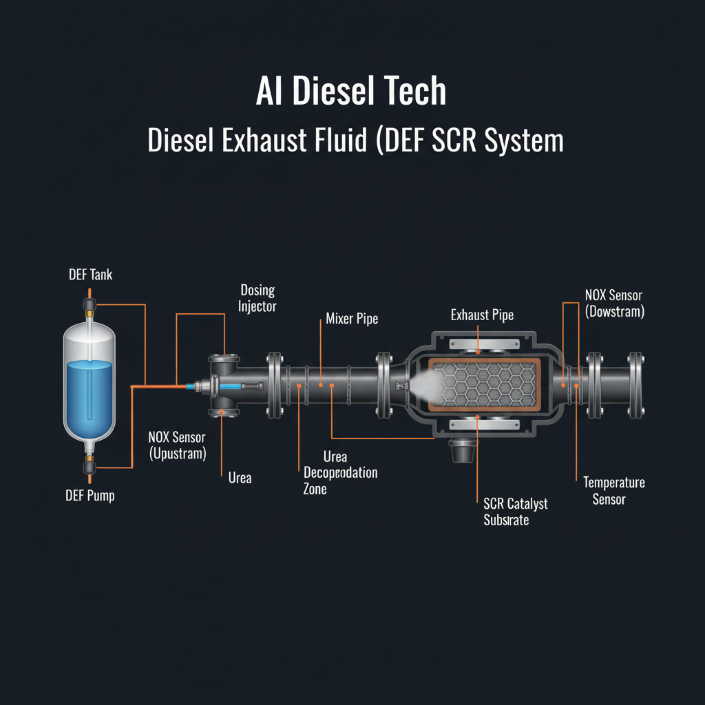
Fault Overview
Detroit DD13 NOx sensor cascade faults present as multiple simultaneous NOx-related codes including upstream sensor faults, downstream sensor faults, and SCR efficiency faults. Upstream NOx sensor failure, shared harness issues, DEF dosing faults producing true NOx elevation, and SCR catalyst degradation are the primary causes. Upstream NOx sensor failure triggering downstream efficiency faults is a documented DD13 pattern — the downstream efficiency fault is a consequence of the upstream sensor fault, not an independent fault. Replacing both sensors and the SCR catalyst for a single upstream sensor fault is the most documented misdiagnosis pattern.
Engine & Platform Coverage
Symptoms
- •DD13 NOx sensor cascade
- •Multiple NOx codes simultaneously
- •Upstream and downstream NOx fault together
- •SCR efficiency fault from NOx cascade
- •DD13 inducement from NOx cascade
Possible Causes
- 1.Upstream NOx sensor failure — upstream sensor failure producing cascade of downstream efficiency faults
- 2.Shared harness issues — shared harness fault producing both sensor faults simultaneously
- 3.DEF dosing faults — DEF dosing fault producing true NOx elevation
- 4.SCR catalyst degradation — SCR catalyst degradation producing true efficiency fault
Diagnostic Flow — FSM Sequence
AI Diesel Tech enforces this evidence-gate sequence. Each gate must pass before advancing.
6 steps locked behind Technician Mode- 1Step 1 — Upstream vs Downstream NOx Comparison: Compare upstream and downstream NOx sensor readings. The upstream sensor should read engine-out NOx. The downstream sensor should read post-SCR NOx. A downstream reading that is higher than the upstream reading confirms a sensor fault — the downstream sensor cannot read higher than the upstream sensor in a functioning system. An upstream sensor that reads zero or implausible values confirms upstream sensor failure.
- 2Step 2 — Sensor Heater Check: Check the NOx sensor heater circuits. A NOx sensor with a failed heater does not reach operating temperature and produces incorrect readings. Confirm heater circuit integrity for both upstream and downstream sensors. A heater fault produces sensor faults that are not corrected by sensor replacement without circuit repair.
- 3Step 3 — DEF Dosing Verification: Verify DEF dosing is correct. A DEF dosing fault producing true NOx elevation produces downstream efficiency faults that are not corrected by sensor replacement. Confirm the dosing system is operating correctly before any sensor replacement.
- 4Step 4 — Isolate Upstream Fault First: Isolate the upstream fault first. Upstream NOx sensor failure triggering downstream efficiency faults is a documented DD13 pattern. Repair the upstream fault before evaluating the downstream sensor. A downstream efficiency fault that clears after upstream sensor repair confirms the cascade pattern.
- 5Step 5 — SCR Efficiency Evaluation: Evaluate SCR efficiency after upstream sensor repair. A true SCR efficiency fault that persists after upstream sensor repair and confirmed dosing requires SCR catalyst assessment. Do not replace the SCR catalyst for an upstream sensor cascade fault.
- 6Step 6 — Sensor Replacement After Proof: Replace sensors only after proof of sensor failure. Confirm circuit integrity and dosing system integrity before sensor replacement. A sensor replaced without proof may be replaced into a circuit fault that will fail the new sensor.
- 7Step 7 — Verify After Repair: Verify NOx sensor readings are plausible after repair. Confirm upstream and downstream NOx readings are consistent with engine operation. Confirm cascade faults do not return after repair.
Unlock the full evidence-gated diagnostic sequence, DVOM test steps, and repair procedures in Technician Mode.
Repair Steps
3 steps locked- 1Repair upstream NOx sensor or circuit first.
- 2Repair heater circuit if heater fault is confirmed.
- 3Correct DEF dosing fault if confirmed.
- 4Replace downstream sensor only if fault persists after upstream repair.
- 5Replace SCR catalyst only if true efficiency fault persists after sensor and dosing repair.
Unlock full diagnostic steps, DVOM tests, and repair procedures.
Full Diagnostic Access
Verification steps, preventative measures, severity guidance, and legacy comparison are available in Technician Mode.
Start Diagnosing This Fault Now
AI Diesel Tech walks you through every evidence gate in the correct order. Choose the plan that fits your shop.
Related Resources
Related Fault Codes
Related Systems
Related Fault Codes
Related Sensor Locations
Common Symptoms
Related Articles
AI Diesel Tech — The Technician's Diagnostic Engine
AI Diesel Tech diagnostic logic is built by an ASE Certified Diesel Technician and engineered for professional shop use. Trusted by technicians nationwide — used in shops, fleets, and training programs.
Summary
The DD13 produces a characteristic NOx cascade where upstream failure triggers downstream faults. The AI Diesel Tech FSM enforces upstream-first isolation before downstream sensor replacement.