
Boost Desired vs Actual Graph Interpretation
Desired vs actual boost is the primary decision tool for turbo performance faults. Turbo replaced based on power complaint without ever graphing desired and actual boost is the most documented misdiagnosis pattern. The FSM converts boost complaints into measurable decision branches.
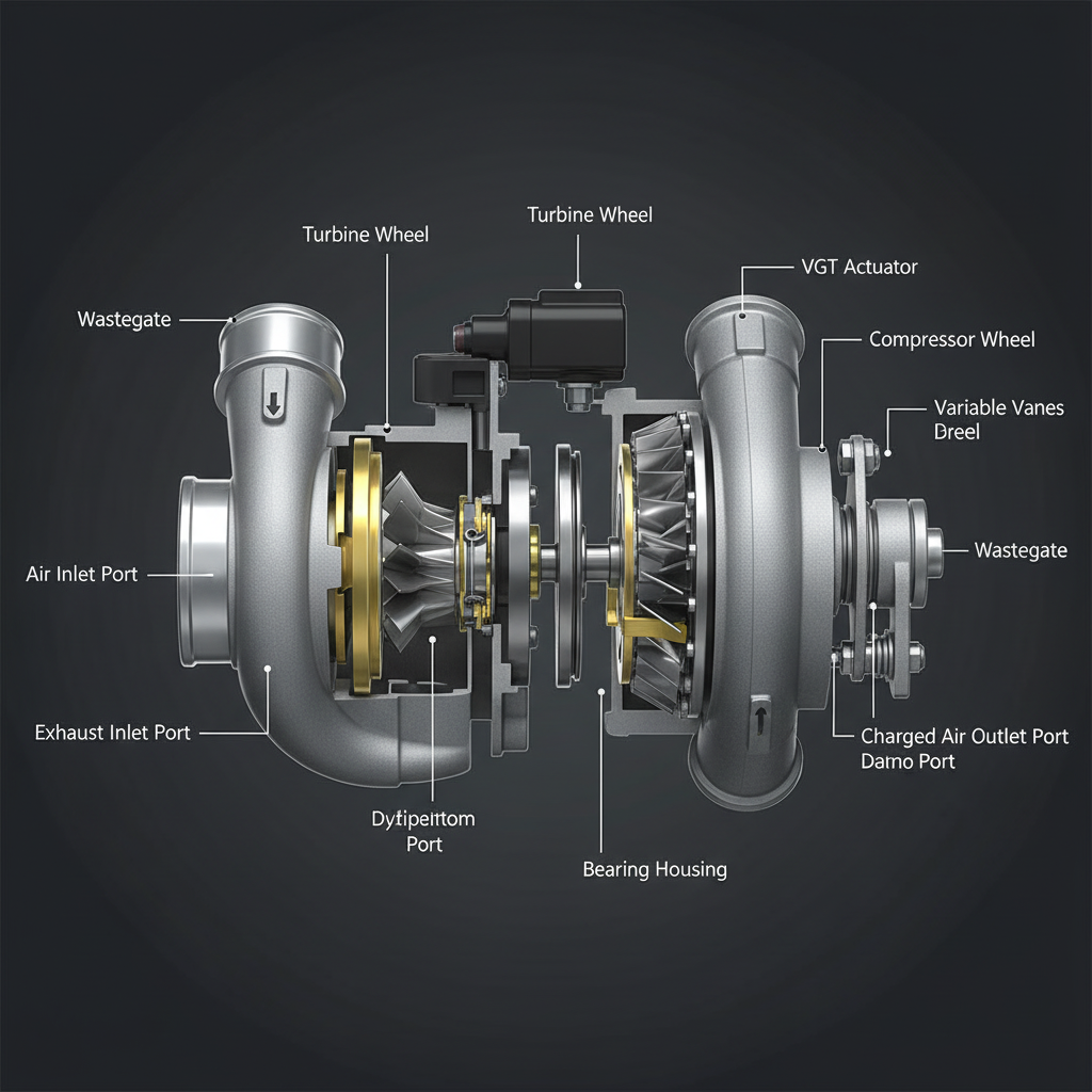
Fault Overview
Boost desired vs actual graph interpretation is a process page for underboost and overboost diagnosis. If actual stays below desired, the causes are leaks, weak turbo response, or restriction. If actual exceeds desired, the causes are stuck VGT closed, control faults, or sensor bias. Turbo replaced based on power complaint without ever graphing desired and actual boost is the most documented misdiagnosis pattern. The desired vs actual boost graph is the primary decision tool that converts a power complaint into a measurable diagnostic branch.
Engine & Platform Coverage
Symptoms
- •Desired vs actual boost deviation
- •How to diagnose underboost with PIDs
- •Boost graph diagnosis
- •Turbo not meeting setpoint
- •Power complaint with no boost code
Possible Causes
- 1.Actual below desired — leaks, weak turbo response, or restriction preventing boost from reaching desired
- 2.Actual above desired — stuck VGT closed, control faults, or sensor bias producing overboost
- 3.Sensor bias — MAP sensor bias producing false actual boost reading
- 4.Actuator fault — VGT actuator fault preventing correct boost control
Diagnostic Flow — FSM Sequence
AI Diesel Tech enforces this evidence-gate sequence. Each gate must pass before advancing.
6 steps locked behind Technician Mode- 1Step 1 — Graph Desired and Actual Boost: Graph desired and actual boost simultaneously under load. KOEO actual should be near atmosphere. A smooth climb under load is expected. Spikes suggest sensing issues. A graph that shows actual consistently below desired confirms underboost. A graph that shows actual consistently above desired confirms overboost.
- 2Step 2 — Note Load Points of Deviation: Note the load points where deviation occurs. Deviation that occurs only at high load suggests a capacity or leak issue. Deviation that occurs at all load points suggests a sensor or actuator fault. Deviation that occurs only at light load suggests a control or actuator fault.
- 3Step 3 — Leak Test If Actual Is Below Desired: Perform a leak test if actual boost is consistently below desired. Pressurize the charge-air system and inspect for leaks at the CAC, boots, and pipes. A charge-air leak reduces actual boost below desired. Repair any leaks found before further diagnosis.
- 4Step 4 — Actuator Freedom Check If Over or Under With No Leak: Check actuator freedom if actual is over or under desired with no leak found. Command the VGT actuator through its full range and confirm position feedback matches commanded position. A VGT actuator that does not respond correctly confirms an actuator fault.
- 5Step 5 — Sensor Proof If Values Are Implausible: Verify sensor integrity if boost values are implausible. A MAP sensor bias producing a false actual boost reading confirms a sensing fault. Compare the MAP sensor reading to a known-good reference. Replace the MAP sensor if bias is confirmed after circuit proof.
- 6Step 6 — Turbo Mechanical Assessment Last: Perform turbo mechanical assessment only after leaks, actuator, and sensor faults are eliminated. Inspect turbo shaft play, wheel condition, and housing for damage. A turbo mechanical assessment is the last step, not the first.
- 7Step 7 — Verify After Repair: Verify desired and actual boost match under load after repair. Confirm the boost complaint is resolved. Monitor for return of boost deviation events over extended operation.
Unlock the full evidence-gated diagnostic sequence, DVOM test steps, and repair procedures in Technician Mode.
Repair Steps
2 steps locked- 1Repair charge-air leaks if found.
- 2Service VGT actuator if actuator fault is confirmed.
- 3Replace MAP sensor if sensor bias is confirmed.
- 4Replace turbo only with mechanical evidence after all upstream causes are eliminated.
Unlock full diagnostic steps, DVOM tests, and repair procedures.
Full Diagnostic Access
Verification steps, preventative measures, severity guidance, and legacy comparison are available in Technician Mode.
Start Diagnosing This Fault Now
AI Diesel Tech walks you through every evidence gate in the correct order. Choose the plan that fits your shop.
Related Resources
Related Fault Codes
Related Systems
Related Fault Codes
Related Sensor Locations
Common Symptoms
Related Articles
AI Diesel Tech — The Technician's Diagnostic Engine
AI Diesel Tech diagnostic logic is built by an ASE Certified Diesel Technician and engineered for professional shop use. Trusted by technicians nationwide — used in shops, fleets, and training programs.
Summary
Desired vs actual boost is the primary decision tool for turbo performance faults. The AI Diesel Tech FSM converts boost complaints into measurable decision branches.