
SPN 172 FMI 4 — Intake Air Temperature Circuit Voltage Below Normal
SPN 172 low-voltage codes need short isolation before inlet-air path conclusions. False hot-inlet conclusions after harness rub-through at the filter box is the most documented misdiagnosis.
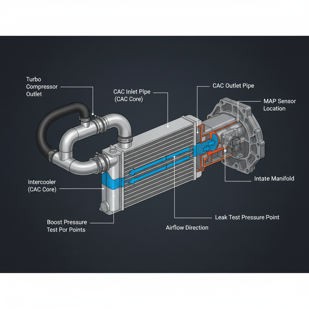
Fault Overview
SPN 172 FMI 4 indicates the intake air temperature circuit voltage is below the normal minimum for sensors mapped as SPN 172. Signal short to ground, failed sensor with internal short, crushed harness at the housing, and moisture bridging are the primary causes. A shorted inlet-air temp circuit typically reports an extreme hot value that can trigger false duct heat-soak conclusions.
Engine & Platform Coverage
Possible Causes
- 1.Signal wire short to ground at housing-mounted sensor wiring and clamp pinch points
- 2.Failed inlet-air temp sensor with internal short to ground
- 3.Crushed harness at filter housing or inlet duct clamp
- 4.Moisture bridging at connector body near filter housing
- 5.Harness rub-through at filter box edges
Wiring & Circuit Notes
Inspect housing-mounted sensor wiring and clamp pinch points — harness rub-through at the filter box is the most common short location for SPN 172 FMI 4. Check for moisture in the connector body.
DVOM Specs & Sensor Tests
Disconnect the inlet-air temp sensor and check the signal wire for short to ground. If the short clears with the sensor disconnected, the sensor is internally shorted. If the short persists, inspect the harness at filter housing and inlet duct clamp pinch points. Verify the reference bus remains healthy with the sensor disconnected.
Diagnostic Flow — FSM Sequence
AI Diesel Tech enforces this evidence-gate sequence. Each gate must pass before advancing.
6 steps locked behind Technician Mode- 1Disconnect SPN 172 mapped sensor connector
- 2Check signal wire for short to ground with sensor disconnected
- 3Verify 5V reference bus remains healthy with sensor disconnected
- 4If short clears with sensor disconnected, replace sensor
- 5If short persists, inspect harness at filter housing and inlet duct clamp pinch points
- 6Repair harness short at identified location
- 7Evaluate duct sealing and heat ingestion only if true high temperature remains after circuit is clean
Unlock the full evidence-gated diagnostic sequence, DVOM test steps, and repair procedures in Technician Mode.
Repair Steps
5 steps locked- 1Disconnect SPN 172 mapped sensor connector
- 2Check signal wire for short to ground with sensor disconnected
- 3Verify 5V reference bus remains healthy with sensor disconnected
- 4If short clears with sensor disconnected, replace sensor
- 5If short persists, inspect harness at filter housing and inlet duct clamp pinch points
- 6Repair harness short at identified location
- 7Evaluate duct sealing and heat ingestion only if true high temperature remains after circuit is clean
Unlock full diagnostic steps, DVOM tests, and repair procedures.
Full Diagnostic Access
Verification steps, preventative measures, severity guidance, and legacy comparison are available in Technician Mode.
Start Diagnosing This Fault Now
AI Diesel Tech walks you through every evidence gate in the correct order. Choose the plan that fits your shop.
Related Resources
Related Systems
Related Fault Codes
Related Sensor Locations
Common Symptoms
Related Articles
AI Diesel Tech — The Technician's Diagnostic Engine
AI Diesel Tech diagnostic logic is built by an ASE Certified Diesel Technician and engineered for professional shop use. Trusted by technicians nationwide — used in shops, fleets, and training programs.
Summary
SPN 172 FMI 4 requires short isolation before any inlet-air path conclusions. The mapped sensor circuit must be proven valid first.