
SPN 1349 FMI 0 — Injector Metering Rail 2 Pressure Above Normal
Rail 2 overpressure on dual-bank systems requires separating a false sensor reading from a true bank-specific overpressure condition before mechanical conclusions. A sensor circuit open or high-signal fault on one bank can create a false overpressure reading that does not reflect actual rail pressure.
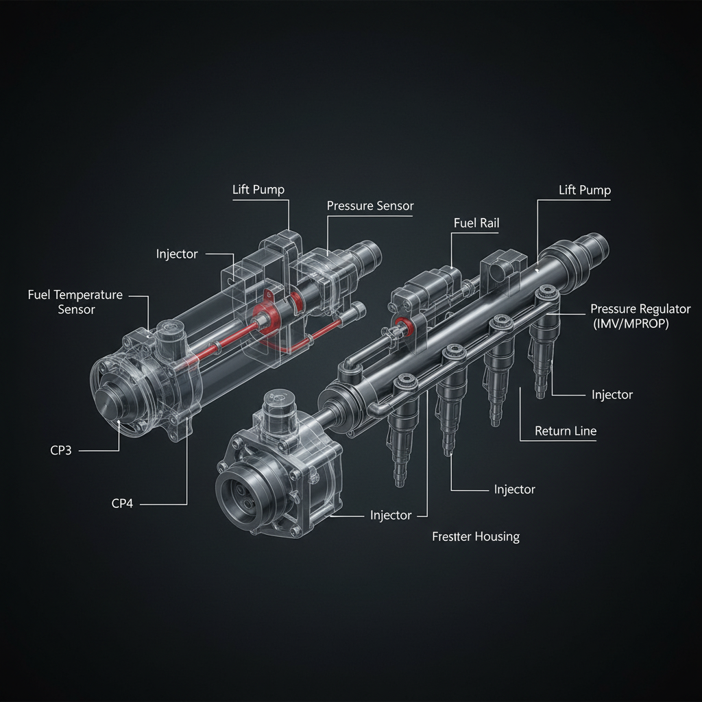
Fault Overview
SPN 1349 FMI 0 indicates the second injector metering rail or bank 2 fuel pressure is above the maximum threshold on dual-rail or banked systems. Bank 2 control valve stuck, return restriction on that bank, sensor bias high, and debris after contamination are the primary causes. False overpressure from a sensor circuit open or high-signal fault on one bank is the most documented pattern.
Engine & Platform Coverage
Possible Causes
- 1.Rail 2 FRP sensor circuit open or high-signal fault creating false overpressure reading
- 2.Bank 2 control valve stuck in high-pressure position
- 3.Return restriction on bank 2 — line, fitting, or return valve restriction
- 4.Sensor bias high from contamination or electrical fault
- 5.Debris after contamination event affecting bank 2 control components
Wiring & Circuit Notes
Validate the rail 2 FRP sensor circuit electrically first — an open or high-signal circuit fault will create a false overpressure reading. Compare both rail sensor circuits for reference and ground integrity.
DVOM Specs & Sensor Tests
Electrically validate both rail pressure sensors. Compare rail 1 versus rail 2 desired and actual pressure. If rail 2 sensor reads high while rail 1 is normal and operating conditions do not support a true overpressure, the rail 2 sensor circuit is the primary suspect. Inspect the bank 2 return path for restriction if sensor is proven accurate.
Diagnostic Flow — FSM Sequence
AI Diesel Tech enforces this evidence-gate sequence. Each gate must pass before advancing.
5 steps locked behind Technician Mode- 1Electrically validate rail 2 FRP sensor — reference, ground, and signal integrity
- 2Compare rail 1 vs rail 2 desired and actual pressure simultaneously
- 3If sensor circuit is proven clean and rail 2 actual is consistently high, proceed to mechanical bank isolation
- 4Inspect bank 2 return path for restriction
- 5Test bank 2 control valve function
- 6Pump path only with clear mechanical evidence after sensor and control valve are proven
Unlock the full evidence-gated diagnostic sequence, DVOM test steps, and repair procedures in Technician Mode.
Repair Steps
4 steps locked- 1Electrically validate rail 2 FRP sensor — reference, ground, and signal integrity
- 2Compare rail 1 vs rail 2 desired and actual pressure simultaneously
- 3If sensor circuit is proven clean and rail 2 actual is consistently high, proceed to mechanical bank isolation
- 4Inspect bank 2 return path for restriction
- 5Test bank 2 control valve function
- 6Pump path only with clear mechanical evidence after sensor and control valve are proven
Unlock full diagnostic steps, DVOM tests, and repair procedures.
Full Diagnostic Access
Verification steps, preventative measures, severity guidance, and legacy comparison are available in Technician Mode.
Start Diagnosing This Fault Now
AI Diesel Tech walks you through every evidence gate in the correct order. Choose the plan that fits your shop.
Related Resources
Related Systems
Related Sensor Locations
Common Symptoms
Related Articles
AI Diesel Tech — The Technician's Diagnostic Engine
AI Diesel Tech diagnostic logic is built by an ASE Certified Diesel Technician and engineered for professional shop use. Trusted by technicians nationwide — used in shops, fleets, and training programs.
Summary
SPN 1349 FMI 0 requires separating a false sensor reading from a true bank-specific overpressure condition. Sensor circuit proof and bank return path inspection precede pump conclusions.