
P0191 — Fuel Rail Pressure Sensor Circuit Range / Performance
P0191 means the fuel rail pressure sensor performance is implausible versus expected behavior. Shared 5V reference bus awareness prevents tunnel vision on one sensor — a shorted companion sensor on the same reference bus can create FRP performance codes without any FRP sensor failure.
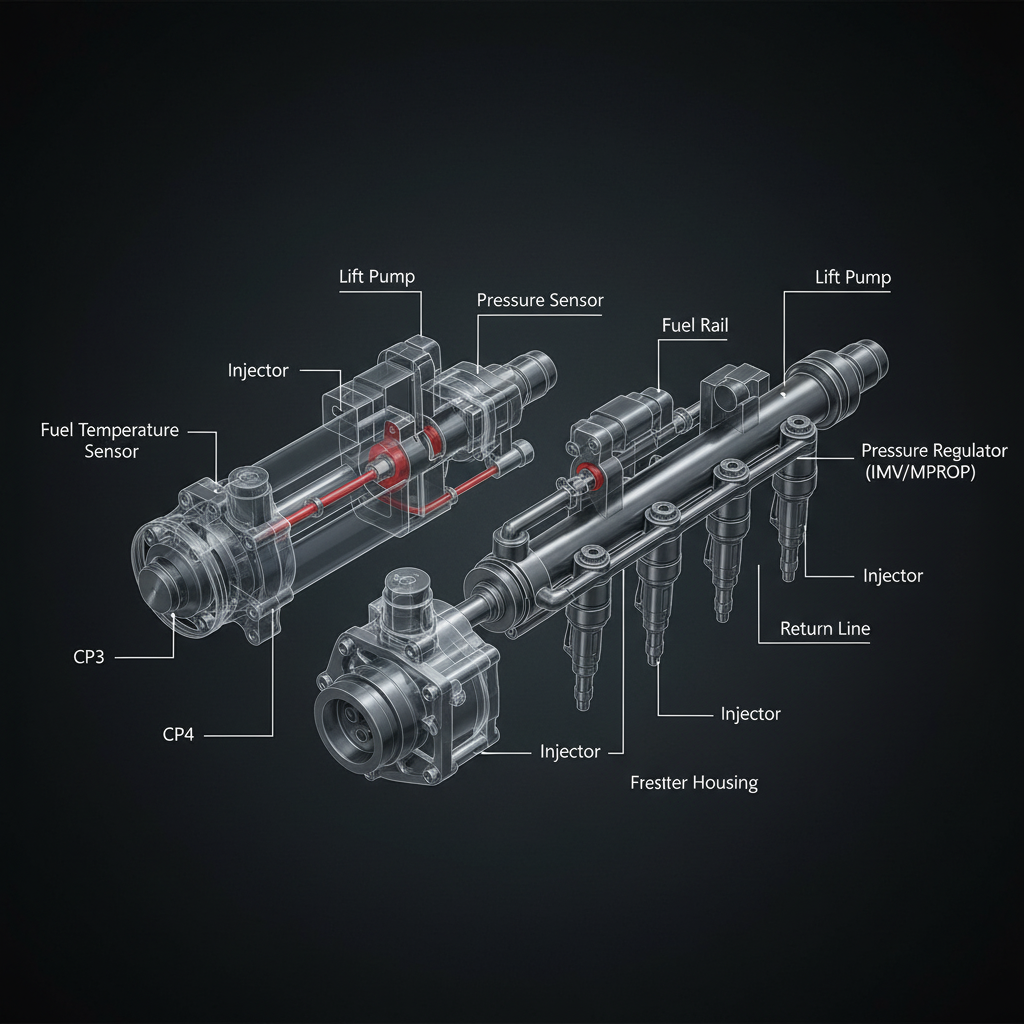
Fault Overview
P0191 indicates the FRP sensor signal is implausible or inconsistently matches expected behavior. Failing FRP sensor, intermittent harness, poor 5V reference, and actual pressure instability from control faults are the primary causes. A 5V reference bus loaded by another shorted sensor creating FRP performance faults is a documented pattern — multi-sensor performance codes appearing together is the key indicator. Replacing the FRP sensor without checking the 5V reference bus produces repeat P0191 if a companion sensor is loading the bus.
Engine & Platform Coverage
Symptoms
- •P0191 fuel rail pressure sensor performance fault active
- •Unstable rail pressure reading
- •FRP range performance fault
- •Multiple sensor performance codes together
- •Intermittent hard start from unstable rail pressure
Possible Causes
- 1.Failing FRP sensor — sensor degradation producing implausible readings
- 2.Intermittent harness — intermittent connection at sensor connector
- 3.Poor 5V reference — 5V reference bus loaded by shorted companion sensor
- 4.Actual pressure instability — control fault producing true pressure instability
- 5.Connector fretting — vibration-induced pin fretting at FRP sensor connector
Diagnostic Flow — FSM Sequence
AI Diesel Tech enforces this evidence-gate sequence. Each gate must pass before advancing.
6 steps locked behind Technician Mode- 1Single Action Gate — Check 5V Reference Bus Health: Check the 5V reference bus health before any FRP sensor replacement. Measure the 5V reference voltage at the FRP sensor connector. A 5V reference below specification with multiple sensor performance codes appearing together confirms a shorted companion sensor loading the bus. Identify and repair the shorted companion sensor before replacing the FRP sensor.
- 2Binary Decision Gate — FRP Electrical Tests: Perform FRP sensor electrical tests. Verify sensor power, ground, and signal integrity. Inspect the sensor connector for fretting corrosion. An intermittent connection at the sensor connector produces intermittent performance faults that appear as sensor failure.
- 3Override Manager — Graph Actual vs Desired Pressure: Graph actual versus desired rail pressure. A sensor that produces dropouts or spikes while desired pressure is stable confirms sensor or circuit intermittent. A sensor that tracks desired pressure but both are unstable confirms a control fault rather than a sensor fault.
- 4Safety Interceptor — Isolate Mechanical Control Only After Sensing is Stable: Isolate mechanical control only after sensing integrity is confirmed. Diagnosing pressure control faults with an unstable sensor produces incorrect conclusions. Confirm the sensor is producing stable, accurate readings before any hydraulic control diagnosis.
- 5Resume Point — Companion Sensor Identification: If 5V reference bus loading is confirmed, identify the companion sensor creating the load. Disconnect sensors on the shared 5V bus one at a time and retest the bus voltage. The sensor that restores bus voltage when disconnected is the shorted companion.
- 6Verification Loop — Post-Repair Sensor Stability Confirmation: After repair, verify FRP sensor produces stable readings that track desired pressure. Confirm P0191 does not return. Monitor for return of unstable rail pressure over extended operation.
- 7Repair Ledger Output — Sensor, Bus, or Harness Decision: Repair shorted companion sensor loading the 5V bus if bus loading is confirmed. Replace FRP sensor after circuit integrity and bus health are confirmed and sensor failure is proven. Repair harness intermittent if connector fretting is found.
Unlock the full evidence-gated diagnostic sequence, DVOM test steps, and repair procedures in Technician Mode.
Repair Steps
2 steps locked- 1Repair shorted companion sensor loading the 5V reference bus.
- 2Repair FRP sensor connector fretting corrosion.
- 3Replace FRP sensor after circuit integrity and bus health are confirmed.
- 4Repair harness intermittent at sensor connector.
Unlock full diagnostic steps, DVOM tests, and repair procedures.
Full Diagnostic Access
Verification steps, preventative measures, severity guidance, and legacy comparison are available in Technician Mode.
Start Diagnosing This Fault Now
AI Diesel Tech walks you through every evidence gate in the correct order. Choose the plan that fits your shop.
Related Resources
Related Fault Codes
Related Systems
Related Sensor Locations
Common Symptoms
Related Articles
AI Diesel Tech — The Technician's Diagnostic Engine
AI Diesel Tech diagnostic logic is built by an ASE Certified Diesel Technician and engineered for professional shop use. Trusted by technicians nationwide — used in shops, fleets, and training programs.
Summary
FRP range and performance is sensing integrity plus control correlation. The AI Diesel Tech FSM enforces shared 5V bus awareness to prevent replacing the wrong sensor on multi-code events.