
Fuel Rail Pressure Decay Test Standard
Rail pressure decay testing, followed by return-flow isolation, identifies the true leak source before any high-pressure component is replaced.
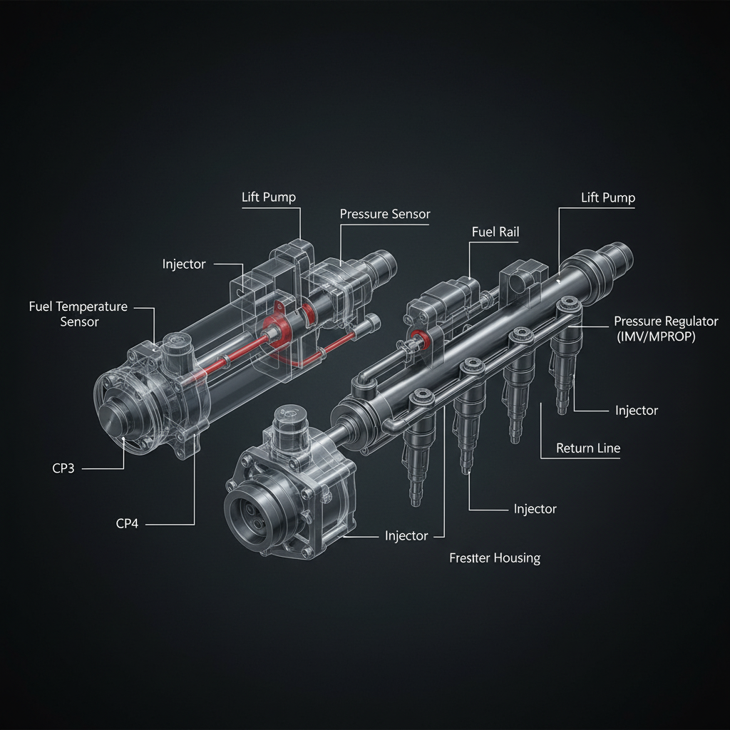
Fault Overview
System process standard for evaluating rail pressure decay (leak-down) after engine shutdown or during controlled conditions to identify internal leakage from injectors, pressure relief valve, or high-pressure pump check valves.
Engine & Platform Coverage
Symptoms
- •Rail pressure decay test
- •Fuel rail leak-down
- •Pressure loss after shutdown
- •Hard start rail pressure
- •Injector leak-down test
Possible Causes
- 1.N/A — process. Rapid decay points to leaking injectors, faulty rail pressure relief valve, or pump outlet check valve leakage.
Wiring & Circuit Notes
Confirm rail pressure sensor circuit is accurate before trusting decay data. Sensor voltage or data rationality must be verified.
DVOM Specs & Sensor Tests
Monitor actual rail pressure with scan tool after high-pressure build and key-off. Record time for pressure to fall from a specified high value to a specified low value. Compare to OEM maximum allowable decay rate. Supplement with return-flow results.
Diagnostic Flow — FSM Sequence
AI Diesel Tech enforces this evidence-gate sequence. Each gate must pass before advancing.
6 steps locked behind Technician Mode- 1Step 1 — Verify Rail Pressure Sensor Accuracy: Verify rail pressure sensor accuracy. Compare to mechanical gauge if available. Sensor voltage or data rationality must be verified before trusting decay data.
- 2Step 2 — Build Rail Pressure to Specified Value: Build rail pressure to specified value (running or via service test).
- 3Step 3 — Key Off or Initiate Decay Monitoring: Key off or initiate decay monitoring. Record time for pressure to fall from a specified high value to a specified low value.
- 4Step 4 — Compare to OEM Maximum Allowable Decay Rate: Compare to OEM maximum allowable decay rate. OEM service information often includes specific decay-time specifications.
- 5Step 5 — Return-Flow Test to Isolate Injectors: If decay is excessive, perform return-flow test to isolate injectors. High return flow on specific cylinders confirms injector leakage.
- 6Step 6 — Check Relief Valve and Pump Check Valve: Check pressure relief valve and pump check valve function per OEM if return flow is normal but decay is still excessive.
- 7Step 7 — Confirm Repair with Repeat Decay Test: Confirm repair with repeat decay test after any service.
Unlock the full evidence-gated diagnostic sequence, DVOM test steps, and repair procedures in Technician Mode.
Full Diagnostic Access
Verification steps, preventative measures, severity guidance, and legacy comparison are available in Technician Mode.
Typical Repair Costs
Replace leaking injectors identified by return flow $300–700 each; replace faulty relief valve $100–300; address pump check valve if indicated — variable. Avoid full high-pressure system replacement without isolation.
Start Diagnosing This Fault Now
AI Diesel Tech walks you through every evidence gate in the correct order. Choose the plan that fits your shop.
Related Systems
Related Sensor Locations
Common Symptoms
Related Articles
AI Diesel Tech — The Technician's Diagnostic Engine
AI Diesel Tech diagnostic logic is built by an ASE Certified Diesel Technician and engineered for professional shop use. Trusted by technicians nationwide — used in shops, fleets, and training programs.
Summary
Use the AI Diesel Tech diagnostic engine to run this code through a structured, evidence-gated sequence and get a confirmed root cause before any parts are replaced.