
Sensor Diagnosis
Crankshaft Sensor Problems
Crankshaft sensor failures cause no-start, stalling, sync loss, and misfires worldwide. This USA-built diagnostic guide covers crank signal logic, cam/crank correlation, harness integrity, and ECM power/ground testing for Cummins, Detroit, Paccar, Volvo, CAT, and International engines.
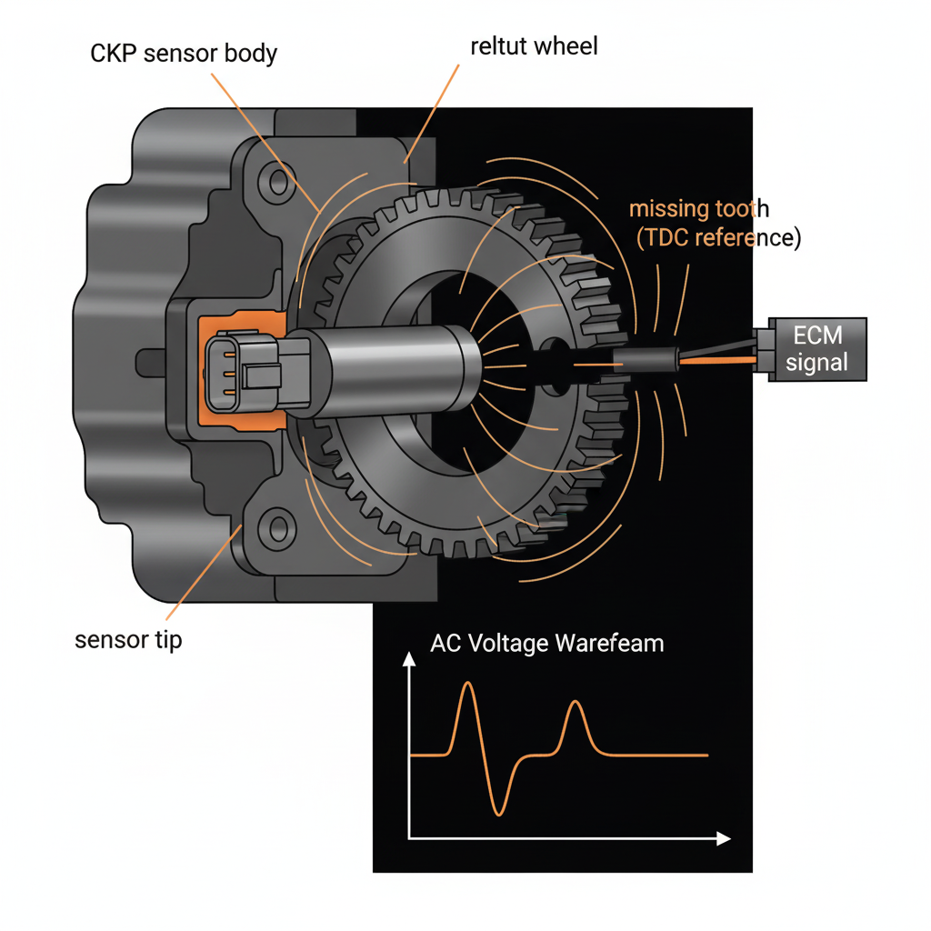
Why This Matters
- ▸A failed crank sensor prevents injection entirely — the ECM will not fire injectors without a valid RPM signal.
- ▸Intermittent crank sensor faults cause stalling at highway speed — a safety hazard that requires immediate diagnosis.
- ▸Cam/crank correlation faults are often caused by wiring issues, not sensor failure — always check harness integrity first.
7-Step Diagnostic Flow
Check RPM signal
SPN 190 (engine speed). With the engine cranking, verify the ECM is receiving an RPM signal. No RPM signal during crank = crank sensor failure, wiring fault, or reluctor wheel damage. An RPM signal that drops to zero intermittently at operating speed = sensor air gap issue or harness chafing.
Check sync state
The ECM requires both crank and cam signals to establish sync before enabling injection. Check sync status with a scan tool — "sync lost" or "sync not achieved" during crank = crank or cam sensor fault. Verify which sensor is causing the sync loss before replacing both.
Check sensor resistance
For magnetic (passive) sensors: measure resistance across the sensor terminals. Spec is typically 800–2,000 Ω. Open circuit = failed sensor. Short circuit = shorted sensor or wiring. For Hall-effect (active) sensors: resistance testing is not valid — test supply voltage and signal output instead.
Check sensor voltage
For Hall-effect sensors: verify 5V or 12V supply at the sensor connector. No supply voltage = wiring fault or ECM output failure. Verify signal output — Hall-effect sensors produce a square wave signal. Use a DVOM in AC voltage mode or a lab scope to verify signal presence during cranking.
Check harness integrity
Crank sensor harness failures are more common than sensor failures. Inspect the harness from the sensor to the ECM for chafing against the engine block, heat damage near the exhaust, and connector corrosion. A harness that passes resistance testing at rest may fail under vibration — wiggle test the harness while monitoring RPM signal.
Check cam/crank correlation
SPN 636 (cam/crank correlation). The ECM compares cam and crank signals to verify engine position. A correlation fault indicates the signals are out of phase — caused by a jumped timing chain, damaged reluctor wheel, or incorrect sensor installation. Verify timing before replacing sensors.
Check ECM power and grounds
ECM power and ground faults cause intermittent sensor signal loss that mimics sensor failure. Verify ECM supply voltage (12–14V) and ground circuit voltage drop (<0.1V). A high-resistance ECM ground causes erratic sensor readings across multiple sensors simultaneously — a key indicator that the ECM ground, not the sensor, is the cause.
Engine-Specific Notes
Cummins ISX / X15
SPN 190 (engine speed), SPN 636 (cam/crank correlation). Cummins X15 uses a magnetic crank sensor. Sensor air gap is critical — spec is 0.020–0.060 in. (0.5–1.5 mm). Air gap too large = weak signal at low RPM. Cummins crank sensor harness failures are common near the flywheel housing where the harness contacts the block.
Detroit DD13 / DD15
Detroit uses a Hall-effect crank sensor. Verify 12V supply and ground before condemning the sensor. Detroit crank sensor failures often present as intermittent no-start that clears after the engine cools — thermal expansion changes the air gap. Detroit cam/crank correlation faults are common after timing chain service.
Paccar MX-13
MX-13 uses a magnetic crank sensor. Sensor resistance spec is 800–1,200 Ω. MX crank sensor harness chafing is common near the front cover — inspect the harness routing carefully. MX cam/crank correlation faults are common after front cover gasket replacement if the cam sensor is disturbed.
Volvo / Mack MP8
Volvo D13 uses a Hall-effect crank sensor. Verify 5V supply at the sensor connector. Volvo crank sensor connector corrosion is common in northern climates — inspect connector pins for green corrosion before condemning the sensor. Volvo cam/crank correlation faults are common after timing belt/chain service.
CAT C13 / C15
CAT uses a magnetic crank sensor. CAT crank sensor air gap spec is 0.030–0.080 in. (0.76–2.0 mm). CAT crank sensor failures are common at high mileage — the reluctor wheel teeth wear and reduce signal amplitude. Check reluctor wheel condition before replacing the sensor.
International A26
A26 shares Cummins crank sensor architecture. Follow Cummins crank sensor logic. A26 crank sensor harness failures are common near the flywheel housing. A26 cam/crank correlation faults are common after front gear train service — verify timing marks before returning to service.
DVOM Test Points
| Test | Spec | Note |
|---|---|---|
| Magnetic sensor resistance | 800–2,000 Ω (varies by OEM) | Open circuit = failed sensor; short circuit = shorted sensor or wiring |
| Hall-effect sensor supply | 5V or 12V at sensor connector | No supply voltage = wiring fault or ECM output failure |
| Sensor signal (AC voltage) | >0.5V AC during cranking (magnetic) | Low AC voltage = air gap too large or weak magnet |
| Harness continuity | <1 Ω from sensor to ECM pin | High resistance = chafed or corroded harness — wiggle test under vibration |
Live Data Parameters to Monitor
Engine Speed (SPN 190)
Smooth signal during crank — dropouts = sensor or harness fault
Sync Status
Sync achieved = both crank and cam signals valid; sync lost = investigate both sensors
Cam/Crank Correlation
In phase = correct timing; out of phase = jumped timing or incorrect sensor installation
Injection Enable Status
Injection enabled only after sync achieved — no sync = no injection
ECM Supply Voltage
12–14V — low voltage causes erratic sensor readings across multiple sensors
RPM Signal Quality
Smooth waveform on lab scope — spikes or dropouts = harness or reluctor wheel issue
Related Fault Codes
Frequently Asked Questions
What are the symptoms of a bad crankshaft sensor?
Common symptoms: (1) No-start — the ECM will not enable injection without a valid crank signal; (2) Stalling at operating speed — an intermittent signal loss causes the ECM to cut injection; (3) Hard start — a weak signal at low cranking RPM causes delayed sync; (4) Rough idle that clears at cruise — an intermittent signal at low RPM; (5) Check engine light with SPN 190 or SPN 636 faults. Intermittent symptoms that worsen when the engine is hot indicate a thermal expansion air gap issue.
How do I test a crankshaft sensor without a scope?
For magnetic sensors: measure resistance (800–2,000 Ω spec). Open or short = failed sensor. For Hall-effect sensors: verify supply voltage (5V or 12V) and ground. Use a DVOM in AC voltage mode during cranking — a magnetic sensor should produce >0.5V AC. If you have a scan tool, monitor engine speed (SPN 190) during cranking — any RPM signal means the sensor is producing output. No RPM signal with correct voltage = failed sensor or harness.
Can a bad crank sensor cause a no-start without a fault code?
Yes. If the crank sensor fails completely before the ECM can log a fault, the engine will crank without starting and may not set a code immediately. The ECM requires a minimum number of failed crank attempts before logging SPN 190. Check for RPM signal during cranking with a scan tool — no RPM signal with no code is still a crank sensor fault. After several failed starts, the code will set.
Master Sensor Diagnosis
The AI Diesel Tech Academy covers crank/cam sensors, sync logic, harness testing, and ECM power/ground diagnosis in depth — with DVOM procedures, live data interpretation, and real-world case studies.
Explore the Academy