
Transmission Input Speed Sensor Circuit Voltage Above Normal
FMI 3 or equivalent on the transmission input speed sensor indicates voltage above the calibrated high threshold — typically an open circuit or short to power. Prove supply, signal activity, and air gap before replacing the sensor.
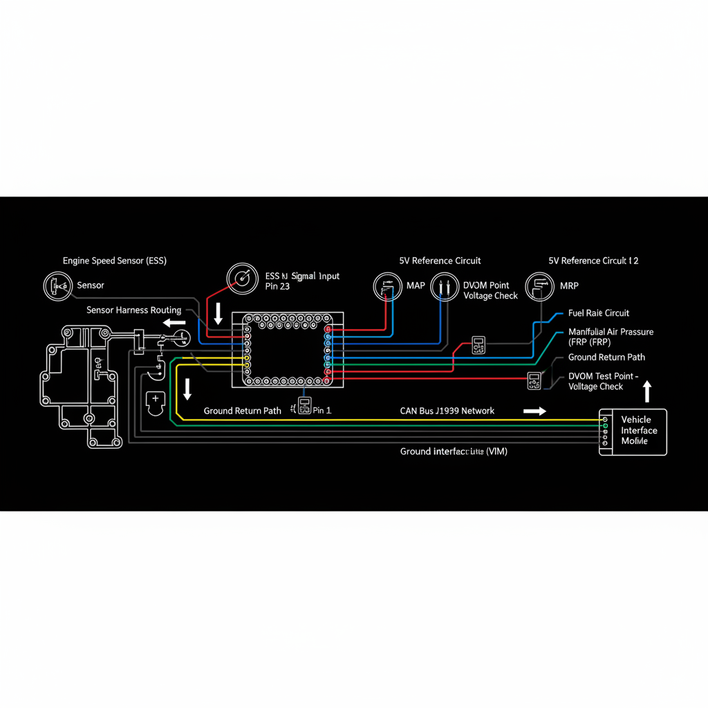
Fault Overview
Circuit fault on the transmission input speed sensor (ISS / turbine speed). Voltage above normal typically indicates an open signal wire, short to power, or internally open sensor. Magnetic sensors generate AC voltage proportional to speed; Hall-effect sensors switch a DC supply. Air gap and tone-wheel condition must be verified.
Engine & Platform Coverage
Symptoms
- •input speed sensor high voltage
- •turbine speed sensor open
- •ISS circuit fault
- •transmission input speed voltage high
- •shift inhibit speed sensor
Possible Causes
- 1.Open signal wire
- 2.Short to power
- 3.Failed sensor internally open
- 4.Poor connector contact
- 5.Damaged tone wheel or reluctor
- 6.Incorrect sensor air gap
- 7.Shared power or ground issues with other speed sensors
Wiring & Circuit Notes
Inspect the input speed sensor connector for corrosion, oil intrusion, and pin tension. Check the signal wire for open or short to battery voltage. Verify sensor supply (if Hall-effect) and ground. Look for chafing near the transmission bell housing or cross-member.
DVOM Specs & Sensor Tests
Magnetic sensors: AC voltage proportional to speed. Hall-effect sensors: DC supply typically 5–12 V; switched output. Air gap per OEM specification. Compare input speed to engine speed and output speed for rationality.
Diagnostic Flow — FSM Sequence
AI Diesel Tech enforces this evidence-gate sequence. Each gate must pass before advancing.
6 steps locked behind Technician Mode- 1Step 1 — Measure Supply Voltage and Ground at the Sensor (Hall-Effect): Measure supply voltage and ground at the sensor connector. Hall-effect sensors require a stable supply; magnetic sensors have no supply pin.
- 2Step 2 — Check Signal Voltage or AC Output While the Shaft Is Rotating: Rotate the input shaft (or observe during cranking/running) and measure signal activity. No signal with shaft turning indicates an open circuit or failed sensor.
- 3Step 3 — Inspect Connector and Harness for Damage or Oil: Inspect the input speed sensor connector for corrosion, oil intrusion, and pin tension. Check the harness for chafing near the bell housing or cross-member.
- 4Step 4 — Verify Tone Wheel Condition and Air Gap: Inspect the tone wheel or reluctor for missing teeth, damage, or debris. Measure air gap and compare to OEM specification.
- 5Step 5 — Perform Continuity and Short-to-Power Tests on the Signal Circuit: With the sensor disconnected, check signal wire continuity from the sensor connector to the TCM and verify no short to battery voltage.
- 6Step 6 — Compare Input Speed Data to Engine Speed and Output Speed: At operating speed, compare input speed to engine speed and output speed for rationality. Implausible ratios indicate a sensor or tone-wheel problem.
- 7Step 7 — Replace the Sensor Only After Circuit and Mechanical Proof: Replace the sensor only after the circuit is proven intact and the tone wheel and air gap are correct. Repair open or shorted wiring first.
Unlock the full evidence-gated diagnostic sequence, DVOM test steps, and repair procedures in Technician Mode.
Full Diagnostic Access
Verification steps, preventative measures, severity guidance, and legacy comparison are available in Technician Mode.
Typical Repair Costs
Repair open or shorted wiring $80–200; clean or replace connector $50–150; adjust or replace sensor $100–300; repair tone wheel if damaged $150–400.
Start Diagnosing This Fault Now
AI Diesel Tech walks you through every evidence gate in the correct order. Choose the plan that fits your shop.
Related Systems
Related Fault Codes
Related Sensor Locations
Common Symptoms
Related Articles
AI Diesel Tech — The Technician's Diagnostic Engine
AI Diesel Tech diagnostic logic is built by an ASE Certified Diesel Technician and engineered for professional shop use. Trusted by technicians nationwide — used in shops, fleets, and training programs.
Summary
Use the AI Diesel Tech diagnostic engine to run this code through a structured, evidence-gated sequence and get a confirmed root cause before any parts are replaced.