
SPN 91 FMI 8 — Accelerator Pedal Position Abnormal Frequency / Update Rate
Abnormal APP update rate or frequency faults are signal-integrity problems — the ECM is receiving the pedal signal but the data quality is compromised by dropouts, noise, or fretting. Intermittent limp-mode events from vibration-related pedal connector fretting are the most documented pattern. Scope or PID graphing under road conditions beats static voltage testing for this fault class.
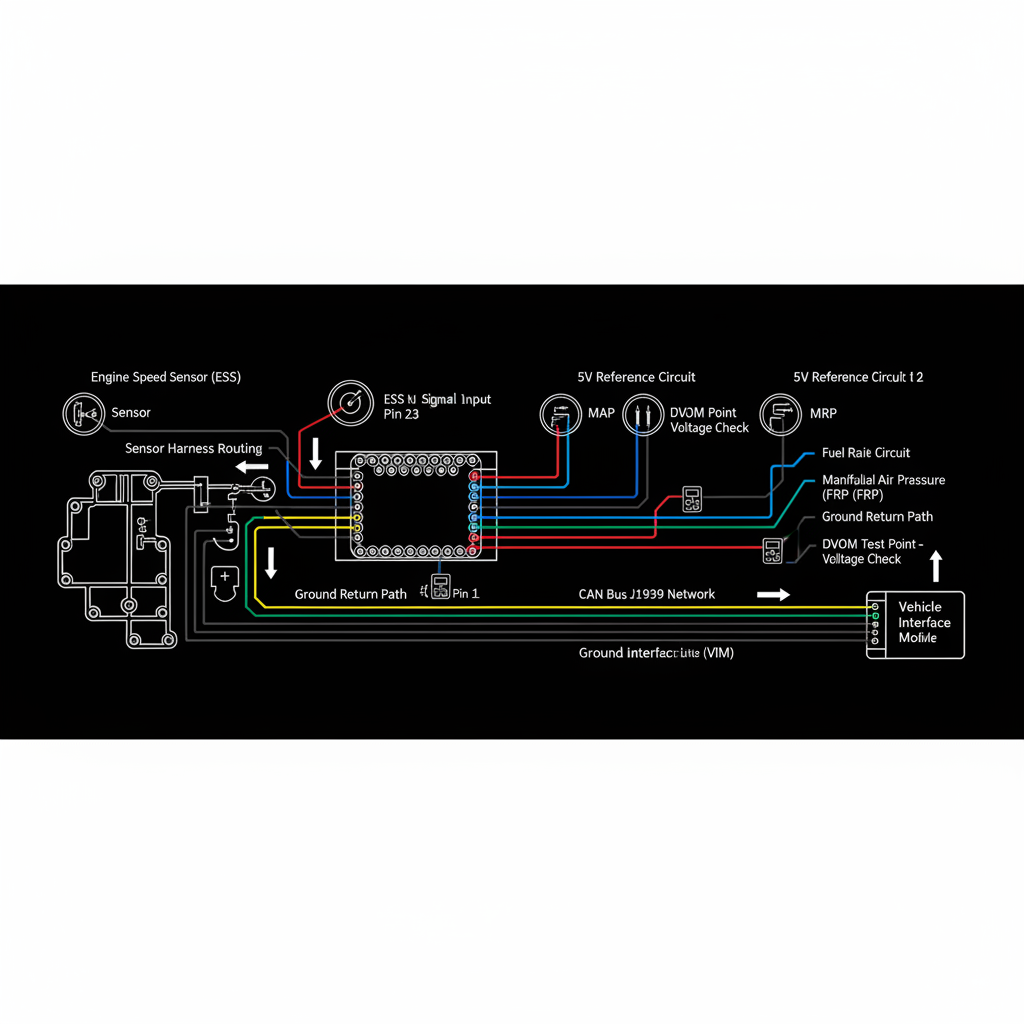
Fault Overview
SPN 91 FMI 8 indicates the accelerator pedal position signal frequency or update rate is abnormal — the ECM monitors the integrity of digital or high-sample-rate APP signals and flags when the data stream becomes erratic, drops out, or fails to update at the expected rate. Intermittent harness, poor grounds, failing pedal module, EMI on signal lines, and connector fretting are the primary causes. Intermittent limp-mode events from vibration-related pedal connector fretting are the most documented pattern.
Engine & Platform Coverage
Possible Causes
- 1.Connector fretting at pedal connector from vibration cycling
- 2.Intermittent harness — micro-breaks under vibration or flex
- 3.Poor chassis ground integrity affecting signal reference
- 4.Failing pedal module with internal signal dropout
- 5.EMI on signal lines from routing near high-current motors or relays
- 6.Shield or drain wire damage on shielded APP harness
Wiring & Circuit Notes
Inspect shield and ground integrity on shielded APP harness runs. Check pedal connector terminal tension — fretting from vibration is the most common cause of intermittent update-rate faults. Verify routing does not pass near high-current motors, solenoids, or relay clusters that generate EMI. Inspect for micro-breaks in harness at flex points near the pedal pivot.
DVOM Specs & Sensor Tests
Watch for dropouts while holding the pedal at a steady position and while sweeping through full travel. Scope or PID integrity monitoring reveals intermittent signal loss that static voltage testing misses entirely. A clean static voltage with intermittent dropouts under vibration confirms a connector or harness fault rather than a failed sensor track.
Diagnostic Flow — FSM Sequence
AI Diesel Tech enforces this evidence-gate sequence. Each gate must pass before advancing.
5 steps locked behind Technician Mode- 1Graph APP signal quality at steady pedal position and through full sweep under road load
- 2Perform wiggle test at pedal connector and along harness while monitoring PID for dropouts
- 3Verify power supply and ground stability at pedal connector under cranking and running conditions
- 4Inspect connector terminal tension and fretting evidence at pedal connector
- 5Check harness routing for proximity to EMI sources — motors, relays, alternator
- 6Replace pedal module or connector only after circuit integrity is proven insufficient
Unlock the full evidence-gated diagnostic sequence, DVOM test steps, and repair procedures in Technician Mode.
Repair Steps
4 steps locked- 1Graph APP signal quality at steady pedal position and through full sweep under road load
- 2Perform wiggle test at pedal connector and along harness while monitoring PID for dropouts
- 3Verify power supply and ground stability at pedal connector under cranking and running conditions
- 4Inspect connector terminal tension and fretting evidence at pedal connector
- 5Check harness routing for proximity to EMI sources — motors, relays, alternator
- 6Replace pedal module or connector only after circuit integrity is proven insufficient
Unlock full diagnostic steps, DVOM tests, and repair procedures.
Full Diagnostic Access
Verification steps, preventative measures, severity guidance, and legacy comparison are available in Technician Mode.
Start Diagnosing This Fault Now
AI Diesel Tech walks you through every evidence gate in the correct order. Choose the plan that fits your shop.
Related Resources
AI Diesel Tech — The Technician's Diagnostic Engine
AI Diesel Tech diagnostic logic is built by an ASE Certified Diesel Technician and engineered for professional shop use. Trusted by technicians nationwide — used in shops, fleets, and training programs.
Summary
SPN 91 FMI 8 is a signal-integrity diagnosis at the pedal circuit. Scope or PID graphing under road conditions, wiggle testing, and connector fretting inspection must be completed before the pedal module is condemned.