
SPN 636 FMI 8 — Crankshaft Speed Abnormal Frequency
SPN 636 FMI 8 means the crankshaft position signal frequency is outside the expected range for engine conditions. Abnormal crank frequency is signal integrity and target condition diagnosis — noise-versus-mechanical target branch control prevents replacing the sensor for a shielding or ground fault.
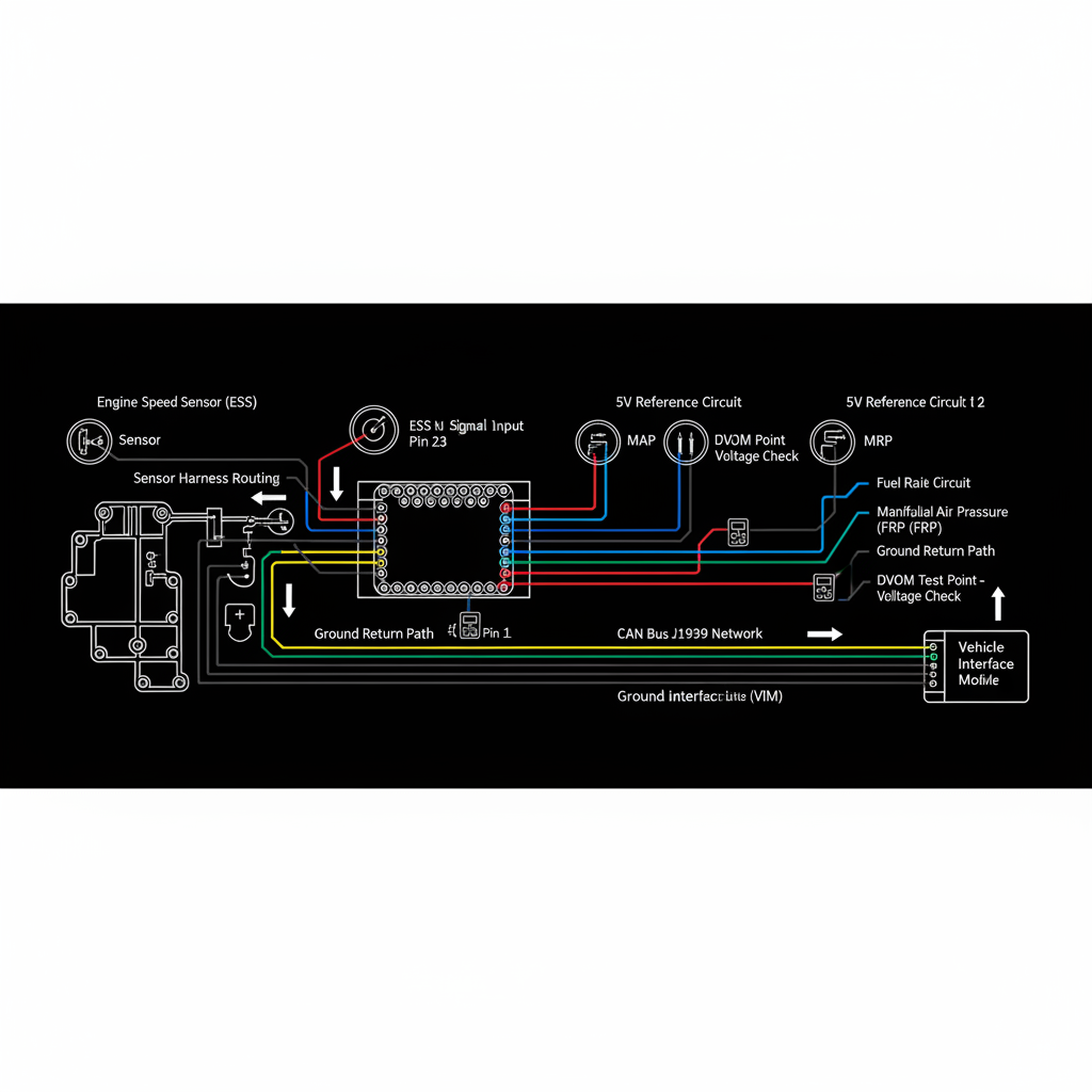
Fault Overview
FMI 8 on crankshaft speed indicates the CKP signal frequency is outside the expected range, suggesting noise, missing teeth detection errors, or signal integrity problems. Shield or ground issues, damaged reluctor, intermittent contact, electromagnetic noise, and loose sensor mount are the primary causes. False overspeed or underspeed events from a noisy CKP signal are a documented pattern. A scope is preferred over DVOM for frequency diagnosis — spikes or dropouts that indicate integrity issues are visible on a scope but may be missed by DVOM. Shield continuity and clean sensor return grounds are critical for CKP signal integrity.
Engine & Platform Coverage
Symptoms
- •SPN 636 FMI 8 crank abnormal frequency
- •CKP noise or signal integrity fault
- •False RPM spike or underspeed event
- •Sync error from frequency fault
- •Cam-crank correlation fault following frequency fault
Possible Causes
- 1.Shield or ground issues — CKP shield or return ground fault producing noise
- 2.Damaged reluctor — damaged tone ring teeth producing frequency errors
- 3.Intermittent contact — intermittent sensor contact producing frequency spikes
- 4.Electromagnetic noise — external noise source coupling into CKP circuit
- 5.Loose sensor mount — sensor movement producing frequency errors
Diagnostic Flow — FSM Sequence
AI Diesel Tech enforces this evidence-gate sequence. Each gate must pass before advancing.
6 steps locked behind Technician Mode- 1Single Action Gate — Secure Mount and Inspect Target: Confirm the CKP sensor mount is secure and inspect the tone ring or reluctor. A loose sensor mount produces frequency errors from sensor movement. Inspect the tone ring for damaged, missing, or bent teeth. A damaged tone ring produces repeating frequency errors at the damaged tooth location.
- 2Binary Decision Gate — Shield and Ground Integrity: Check CKP shield continuity and sensor return ground integrity. Shield continuity and clean sensor return grounds are critical for CKP signal integrity. A shield fault or poor return ground allows electromagnetic noise to couple into the CKP circuit and produce frequency errors.
- 3Override Manager — Scope the CKP Signal: Scope the CKP signal at operating speed. Frequency should track engine speed cleanly. Spikes or dropouts indicate integrity issues. A scope is preferred over DVOM for frequency diagnosis — spikes that indicate noise are visible on a scope but may be missed by DVOM.
- 4Safety Interceptor — Compare Crank and Cam Correlation: Compare crank and cam correlation. A crank frequency fault with a clean cam signal confirms the fault is isolated to the crank sensing path. A crank frequency fault with a simultaneous cam fault suggests a shared circuit or ground fault.
- 5Resume Point — Wiring Repair Before ECM Conclusions: Repair wiring shield and ground faults before any ECM conclusions. A noisy CKP signal from a shield or ground fault produces frequency errors that appear as sensor failure. Confirm wiring integrity before sensor or ECM replacement.
- 6Verification Loop — Post-Repair Frequency Stability Confirmation: After repair, verify CKP frequency tracks engine speed cleanly at all operating speeds. Confirm SPN 636 FMI 8 does not return. Monitor for return of false overspeed or underspeed events.
- 7Repair Ledger Output — Shield, Ground, Sensor, or Tone Ring Decision: Repair shield or ground fault if confirmed. Service tone ring if damage is confirmed. Replace CKP sensor after shield, ground, and tone ring integrity are confirmed and sensor failure is proven. Do not replace ECM for frequency errors without exhausting wiring and target diagnosis.
Unlock the full evidence-gated diagnostic sequence, DVOM test steps, and repair procedures in Technician Mode.
Repair Steps
2 steps locked- 1Repair CKP shield or return ground fault.
- 2Service tone ring if damage is confirmed.
- 3Replace CKP sensor after shield, ground, and tone ring integrity are confirmed.
- 4Identify and eliminate external electromagnetic noise source if confirmed.
Unlock full diagnostic steps, DVOM tests, and repair procedures.
Full Diagnostic Access
Verification steps, preventative measures, severity guidance, and legacy comparison are available in Technician Mode.
Start Diagnosing This Fault Now
AI Diesel Tech walks you through every evidence gate in the correct order. Choose the plan that fits your shop.
Related Resources
Related Fault Codes
AI Diesel Tech — The Technician's Diagnostic Engine
AI Diesel Tech diagnostic logic is built by an ASE Certified Diesel Technician and engineered for professional shop use. Trusted by technicians nationwide — used in shops, fleets, and training programs.
Summary
Abnormal crank frequency is signal integrity and target condition diagnosis. The AI Diesel Tech FSM enforces noise-versus-mechanical target branch control before ECM conclusions.