
SPN 597 FMI 2 — Service Brake Circuit / Pressure Data Erratic
SPN 597 FMI 2 means the service brake signal or pressure-related brake input is erratic depending on OEM implementation. Service brake input faults are signal authenticity diagnostics with safety impact. The FSM prevents powertrain misdiagnosis from brake-input noise.
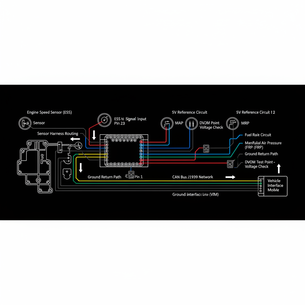
Fault Overview
FMI 2 on service brake circuit or pressure data indicates the ECM detected an erratic or implausible service brake input. Failed switch or pressure sensor, air system issues affecting the pressure switch, and wiring intermittents are the primary causes. Intermittent cruise disengagement and unexpected inhibit logic from noisy brake inputs are documented patterns. Confirming status changes with brake application and monitoring for smooth pressure sensor response without dropouts are the most efficient first steps.
Engine & Platform Coverage
Symptoms
- •SPN 597 FMI 2 service brake signal intermittent
- •Brake pressure sensor erratic
- •Brake input fault derate
- •Intermittent cruise disengage from brake input noise
- •Unexpected inhibit logic from noisy brake input
Possible Causes
- 1.Failed switch or pressure sensor — brake switch or pressure sensor failure producing erratic input
- 2.Air system issues — air system fault affecting pressure switch operation
- 3.Wiring intermittents — harness intermittent producing erratic brake input
Diagnostic Flow — FSM Sequence
AI Diesel Tech enforces this evidence-gate sequence. Each gate must pass before advancing.
6 steps locked behind Technician Mode- 1Single Action Gate — Apply/Release Monitoring: Monitor the service brake input status during brake apply and release. The status should change cleanly with brake application. A status that does not change or changes erratically confirms a switch, sensor, or circuit fault. For pressure-based systems, monitor for smooth pressure response without dropouts during apply and release.
- 2Binary Decision Gate — Circuit Checks: Perform circuit checks on the service brake input circuit. Confirm reference voltage, ground, and signal circuit integrity at the switch or sensor connector. A circuit fault producing erratic input requires circuit repair.
- 3Override Manager — Pneumatic or Hydraulic Integrity Check: Check pneumatic or hydraulic integrity if the fault is pressure-based. An air system fault affecting pressure switch operation produces erratic brake input that is not corrected by switch replacement. Confirm air system pressure is adequate and stable. Inspect for air leaks at the brake valve and pressure switch connections.
- 4Safety Interceptor — Replace Sensor or Switch After Proof: Replace the sensor or switch only after proof of failure. Confirm circuit integrity and pneumatic or hydraulic integrity before sensor or switch replacement. A sensor or switch replaced without proof may be replaced into a circuit or system fault that will fail the new component.
- 5Resume Point — Brake Valve Service If Mechanically Required: Perform brake valve service if mechanical fault is confirmed. A brake valve that produces erratic pressure output requires valve service. Confirm brake valve operation per OEM procedure before any valve replacement.
- 6Verification Loop — Post-Repair Input Confirmation: After repair, verify the service brake input changes cleanly with brake application. Confirm SPN 597 FMI 2 does not return. Confirm cruise and inhibit logic returns to normal after repair.
- 7Repair Ledger Output — Switch, Sensor, Circuit, or Valve Decision: Replace switch or sensor if failure is confirmed after circuit proof. Repair circuit if intermittent connection is confirmed. Service brake valve if mechanical fault is confirmed. Repair air system if air system fault is confirmed.
Unlock the full evidence-gated diagnostic sequence, DVOM test steps, and repair procedures in Technician Mode.
Repair Steps
2 steps locked- 1Replace switch or sensor if failure is confirmed after circuit proof.
- 2Repair circuit if intermittent connection is confirmed.
- 3Service brake valve if mechanical fault is confirmed.
- 4Repair air system if air system fault is confirmed.
Unlock full diagnostic steps, DVOM tests, and repair procedures.
Full Diagnostic Access
Verification steps, preventative measures, severity guidance, and legacy comparison are available in Technician Mode.
Start Diagnosing This Fault Now
AI Diesel Tech walks you through every evidence gate in the correct order. Choose the plan that fits your shop.
Related Resources
Related Fault Codes
Related Systems
Related Fault Codes
Related Sensor Locations
Common Symptoms
Related Articles
AI Diesel Tech — The Technician's Diagnostic Engine
AI Diesel Tech diagnostic logic is built by an ASE Certified Diesel Technician and engineered for professional shop use. Trusted by technicians nationwide — used in shops, fleets, and training programs.
Summary
Service brake input faults are signal authenticity diagnostics with safety impact. The AI Diesel Tech FSM prevents powertrain misdiagnosis from brake-input noise.