
SPN 51 FMI 2 — Engine Throttle Position Data Erratic
SPN 51 FMI 2 means the throttle plate position feedback is erratic on systems with intake throttle actuators. Carbon buildup preventing stable control is as common as sensor failure — the carbon versus electrical split is the required first diagnostic branch.
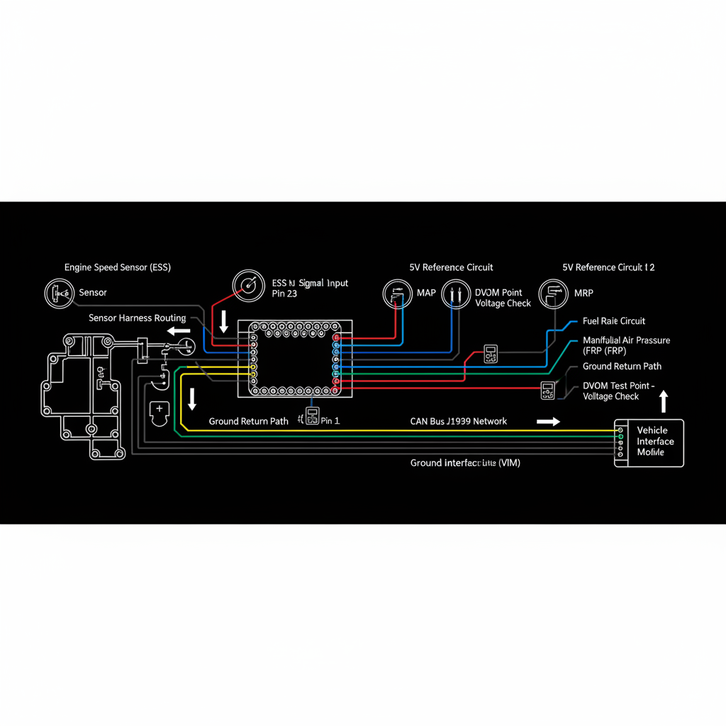
Fault Overview
FMI 2 on the throttle position circuit indicates the position feedback is erratic or inconsistently follows the commanded position. Carboned throttle plate preventing stable control, failed position sensor, actuator wear, and harness intermittents are the primary causes. Carbon buildup creates false 'sensor erratic' conclusions when the actual problem is mechanical restriction preventing the throttle from following the command signal. Replacing the throttle assembly without cleaning and verifying control is the most common unnecessary repair on this fault.
Engine & Platform Coverage
Symptoms
- •Intake throttle erratic fault active
- •Throttle plate sensor fault
- •Regen throttle actuator code
- •Unstable idle from throttle control issue
- •Regen performance affected by throttle fault
- •EGR flow interaction from throttle fault
Possible Causes
- 1.Carboned throttle plate — carbon buildup preventing stable control
- 2.Failed position sensor — internal sensor failure
- 3.Actuator wear — motor or gear wear producing erratic movement
- 4.Harness intermittents — connector heat or oil exposure
- 5.Pin fretting — connector pin fretting from vibration
Diagnostic Flow — FSM Sequence
AI Diesel Tech enforces this evidence-gate sequence. Each gate must pass before advancing.
6 steps locked behind Technician Mode- 1Single Action Gate — Command Sweep Test: Command a throttle sweep via scan tool and observe position feedback. If the throttle moves but position feedback is erratic during movement, the sensor or harness is suspect. If the throttle does not move smoothly through the full range, carbon buildup or mechanical restriction is the primary suspect.
- 2Binary Decision Gate — Visual Carbon Inspection: Inspect the throttle bore and plate for carbon buildup. Carbon buildup from EGR and crankcase ventilation is a documented cause of throttle control instability that produces false erratic position codes. Significant carbon buildup requires cleaning before any sensor or assembly decision.
- 3Override Manager — Circuit Integrity Check: Verify throttle position sensor circuit integrity. Inspect the throttle body connector for heat and oil exposure. Verify sensor supply, ground, and signal. Pin fretting from vibration is a documented cause of intermittent position faults.
- 4Safety Interceptor — Clean and Retest: Clean the throttle bore and plate per OEM procedure and retest. If the throttle now moves smoothly and position feedback is stable after cleaning, carbon was the cause. If erratic behavior persists after cleaning, proceed to sensor and actuator evaluation.
- 5Resume Point — Actuator Wear Assessment: If cleaning does not resolve the fault, assess actuator wear. A worn motor or gear produces erratic movement that the position sensor accurately reports as erratic — the sensor is not the fault in this case.
- 6Verification Loop — Post-Repair Control Confirmation: After repair, verify throttle moves smoothly through the full range and position feedback is stable. Confirm regen performance returns to normal after repair.
- 7Repair Ledger Output — Clean vs Replace Decision: Clean throttle body if carbon is the cause. Replace throttle assembly if sensor or actuator failure is confirmed after cleaning. Do not replace assembly for carbon buildup alone.
Unlock the full evidence-gated diagnostic sequence, DVOM test steps, and repair procedures in Technician Mode.
Repair Steps
2 steps locked- 1Clean throttle bore and plate per OEM procedure.
- 2Repair connector heat or oil damage.
- 3Replace throttle assembly if sensor or actuator failure is confirmed after cleaning.
- 4Repair harness intermittents found by circuit check.
Unlock full diagnostic steps, DVOM tests, and repair procedures.
Full Diagnostic Access
Verification steps, preventative measures, severity guidance, and legacy comparison are available in Technician Mode.
Start Diagnosing This Fault Now
AI Diesel Tech walks you through every evidence gate in the correct order. Choose the plan that fits your shop.
Related Resources
Related Fault Codes
AI Diesel Tech — The Technician's Diagnostic Engine
AI Diesel Tech diagnostic logic is built by an ASE Certified Diesel Technician and engineered for professional shop use. Trusted by technicians nationwide — used in shops, fleets, and training programs.
Summary
SPN 51 FMI 2 is often carbon plus feedback integrity. The AI Diesel Tech FSM enforces the carbon versus electrical split before throttle assembly replacement.