
SPN 173 FMI 3 — Exhaust Gas Temperature Circuit Voltage Above Normal
EGT high-voltage codes are open-circuit heat-zone diagnostics first. Major fueling or AT work performed because one EGT circuit was open and reporting false cold exhaust is the most documented misdiagnosis.
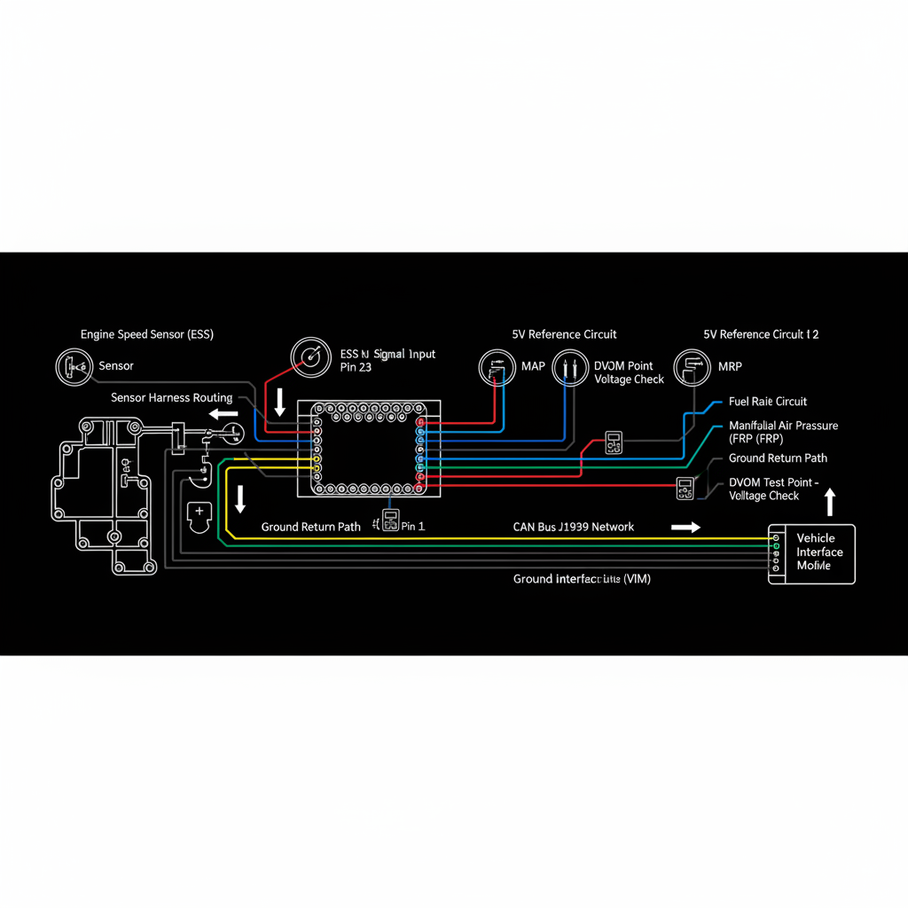
Fault Overview
SPN 173 FMI 3 indicates the exhaust gas temperature sensor circuit voltage is above the normal maximum — an open circuit or high-signal class fault. Open circuit, failed probe, unplugged connector, brittle heat-zone harness, and burnt pins are the primary causes. An open EGT circuit typically reports an extreme cold value — multi-EGT correlation quickly identifies the dead sensor.
Engine & Platform Coverage
Possible Causes
- 1.Open circuit from brittle heat-zone harness insulation failure
- 2.Failed EGT probe with internal open element
- 3.Unplugged connector after exhaust or AT service
- 4.Burnt pins at connector near manifold or AT package
- 5.Clamp abrasion on heat sleeves near exhaust components
Wiring & Circuit Notes
Inspect heat sleeves and clamp abrasion points near manifolds and AT packages. Check connectors for burnt pins — heat-zone connectors are prone to pin damage. Multi-EGT correlation identifies the dead sensor quickly: the sensor reading extreme cold while neighbors read plausible values is the open circuit.
DVOM Specs & Sensor Tests
Identify which EGT PID is reading invalid (extreme cold while neighbors are plausible). Confirm 5V reference, ground, and signal at the identified sensor connector. Open circuits will not respond to actual exhaust temperature changes. Replace the sensor and pigtail/harness after circuit is proven. Reassess thermal strategy after sensing is valid.
Diagnostic Flow — FSM Sequence
AI Diesel Tech enforces this evidence-gate sequence. Each gate must pass before advancing.
5 steps locked behind Technician Mode- 1Identify which EGT PID is reading invalid using multi-EGT correlation
- 2Inspect connector for burnt pins and heat sleeve for abrasion damage
- 3Verify 5V reference and ground at identified sensor connector
- 4Check signal wire continuity from sensor to ECM
- 5Replace EGT sensor and pigtail/harness after circuit is proven
- 6Reassess thermal strategy and AT behavior after sensing is valid
Unlock the full evidence-gated diagnostic sequence, DVOM test steps, and repair procedures in Technician Mode.
Repair Steps
4 steps locked- 1Identify which EGT PID is reading invalid using multi-EGT correlation
- 2Inspect connector for burnt pins and heat sleeve for abrasion damage
- 3Verify 5V reference and ground at identified sensor connector
- 4Check signal wire continuity from sensor to ECM
- 5Replace EGT sensor and pigtail/harness after circuit is proven
- 6Reassess thermal strategy and AT behavior after sensing is valid
Unlock full diagnostic steps, DVOM tests, and repair procedures.
Full Diagnostic Access
Verification steps, preventative measures, severity guidance, and legacy comparison are available in Technician Mode.
Start Diagnosing This Fault Now
AI Diesel Tech walks you through every evidence gate in the correct order. Choose the plan that fits your shop.
Related Resources
Related Systems
Related Fault Codes
Related Sensor Locations
Common Symptoms
Related Articles
AI Diesel Tech — The Technician's Diagnostic Engine
AI Diesel Tech diagnostic logic is built by an ASE Certified Diesel Technician and engineered for professional shop use. Trusted by technicians nationwide — used in shops, fleets, and training programs.
Summary
SPN 173 FMI 3 is an open-circuit EGT diagnosis. Multi-EGT correlation identifies the dead sensor — circuit proof is required before any fueling or AT thermal-path work.