
SPN 1485 FMI 3 — ECM Main Relay Circuit Voltage Above Normal
Main relay high-voltage codes are open control/feed diagnostics first. ECM replaced for a failed main relay or open control feed is the most documented misdiagnosis on this fault class.
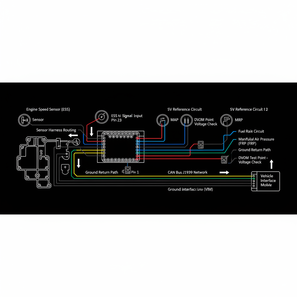
Fault Overview
SPN 1485 FMI 3 is an ECM main power relay control or monitor circuit voltage above normal or open class. Open control wire, failed relay coil open, unplugged relay, blown control fuse, and poor ignition feed are the primary causes. Relay-circuit proof is mandatory before ECM condemnation.
Engine & Platform Coverage
Symptoms
- •ECM main relay open circuit fault active
- •Main power relay high voltage indication
- •Intermittent hard no-comm with relay open pattern
- •ECM power dropout events
- •No-start from controller power loss
Possible Causes
- 1.Open control wire between ignition feed and relay coil
- 2.Failed relay coil — open internal path
- 3.Unplugged relay at relay center
- 4.Blown control fuse in ignition feed path
- 5.Poor ignition feed connection at relay base
Diagnostic Flow — FSM Sequence
AI Diesel Tech enforces this evidence-gate sequence. Each gate must pass before advancing.
5 steps locked behind Technician Mode- 1Single Action Gate — Key-On Control Voltage: With key on, measure voltage at the relay coil control terminal. Confirm ignition feed voltage is present at the coil. Absent voltage indicates an open control wire, blown fuse, or failed ignition feed.
- 2Binary Decision Gate — Load-Side Power at ECM: Measure load-side voltage at the ECM power supply cavity with relay energized. Absent load-side voltage with control voltage present indicates a failed relay or open load circuit.
- 3Override Manager — Coil and Continuity Checks: With relay removed, measure coil resistance. Compare to OEM specification. An open coil reading confirms relay failure. Check continuity of control wire from ignition feed to relay base.
- 4Safety Interceptor — Relay Replacement After Circuit Proof: Replace relay after confirming control circuit and load circuit are intact. Install a known-good relay and verify ECM power is restored before any ECM diagnosis.
- 5Resume Point — ECM Path Only If Power Remains Absent: Proceed to ECM diagnosis only if power remains absent with a forced good feed directly to the ECM power supply cavity. This confirms the ECM itself is not accepting power, not the relay circuit.
- 6Verification Loop — Post-Repair Power Confirmation: After repair, verify stable ECM power key-on and key-off. Confirm no return of main relay circuit faults. Clear faults and verify normal ECM operation.
Unlock the full evidence-gated diagnostic sequence, DVOM test steps, and repair procedures in Technician Mode.
Repair Steps
3 steps locked- 1Repair open control wire between ignition feed and relay coil.
- 2Replace blown control fuse and identify cause of fuse failure.
- 3Replace failed relay after coil resistance confirms open.
- 4Repair poor ignition feed connection at relay base.
- 5Replace ECM only if power remains absent with proven good feed.
Unlock full diagnostic steps, DVOM tests, and repair procedures.
Full Diagnostic Access
Verification steps, preventative measures, severity guidance, and legacy comparison are available in Technician Mode.
Start Diagnosing This Fault Now
AI Diesel Tech walks you through every evidence gate in the correct order. Choose the plan that fits your shop.
Related Resources
Related Fault Codes
Related Systems
Related Fault Codes
Related Sensor Locations
Common Symptoms
Related Articles
AI Diesel Tech — The Technician's Diagnostic Engine
AI Diesel Tech diagnostic logic is built by an ASE Certified Diesel Technician and engineered for professional shop use. Trusted by technicians nationwide — used in shops, fleets, and training programs.
Summary
SPN 1485 FMI 3 is a relay control and feed circuit diagnosis. Main relay high-voltage codes require control voltage, load-side power, and coil continuity proof before any ECM replacement.