
SPN 110 FMI 2 — Engine Coolant Temperature Data Erratic
Erratic ECT signals create intermittent fan cycling, nuisance protection events, and delayed thermal response. The fault is almost always in the sensor or harness — not the cooling system. Thermostat and fan replacement before proving ECT signal stability is the most common misdiagnosis.
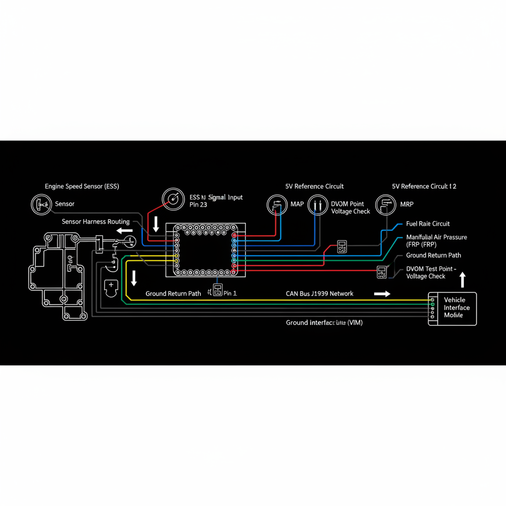
Fault Overview
SPN 110 FMI 2 indicates the engine coolant temperature signal is unstable or implausible — the ECM detects erratic behavior that cannot be rationalized against operating conditions. Failing sensor, connector fretting, intermittent open or short, poor ground, and harness heat damage are the primary causes. Intermittent fan cycling and derate behavior from unstable ECT is the most documented pattern.
Engine & Platform Coverage
Possible Causes
- 1.Failing ECT sensor with intermittent output from internal degradation
- 2.Connector fretting at thermostat housing connector from heat cycling
- 3.Intermittent open or short in harness from heat damage near exhaust or coolant passages
- 4.Poor ground integrity at sensor ground circuit
- 5.Harness heat damage from proximity to exhaust manifold or turbocharger
Wiring & Circuit Notes
Inspect sensor connector at the thermostat housing area — heat cycling causes connector fretting at this location. Perform wiggle test at the connector and along the harness while monitoring the ECT PID. Check for harness heat damage from proximity to exhaust components.
DVOM Specs & Sensor Tests
Graph ECT PID during warm-up and at operating temperature. Look for dropouts or impossible temperature swings — a sudden drop to extreme cold or spike to extreme hot while operating temperature is stable confirms an electrical fault. Use an infrared thermometer at the sensor housing to correlate actual coolant temperature against the PID reading during stable operation.
Diagnostic Flow — FSM Sequence
AI Diesel Tech enforces this evidence-gate sequence. Each gate must pass before advancing.
5 steps locked behind Technician Mode- 1Graph ECT PID during warm-up and at operating temperature — look for dropouts or impossible swings
- 2Perform wiggle test at sensor connector and along harness while monitoring ECT PID
- 3Check ground integrity at ECT sensor ground circuit
- 4Use IR thermometer at sensor housing to correlate actual temperature against PID
- 5Inspect harness for heat damage near exhaust components
- 6Replace sensor and connector after electrical proof — cooling system teardown only if true overheat is confirmed
Unlock the full evidence-gated diagnostic sequence, DVOM test steps, and repair procedures in Technician Mode.
Repair Steps
4 steps locked- 1Graph ECT PID during warm-up and at operating temperature — look for dropouts or impossible swings
- 2Perform wiggle test at sensor connector and along harness while monitoring ECT PID
- 3Check ground integrity at ECT sensor ground circuit
- 4Use IR thermometer at sensor housing to correlate actual temperature against PID
- 5Inspect harness for heat damage near exhaust components
- 6Replace sensor and connector after electrical proof — cooling system teardown only if true overheat is confirmed
Unlock full diagnostic steps, DVOM tests, and repair procedures.
Full Diagnostic Access
Verification steps, preventative measures, severity guidance, and legacy comparison are available in Technician Mode.
Start Diagnosing This Fault Now
AI Diesel Tech walks you through every evidence gate in the correct order. Choose the plan that fits your shop.
Related Resources
AI Diesel Tech — The Technician's Diagnostic Engine
AI Diesel Tech diagnostic logic is built by an ASE Certified Diesel Technician and engineered for professional shop use. Trusted by technicians nationwide — used in shops, fleets, and training programs.
Summary
SPN 110 FMI 2 is a sensor and harness integrity diagnosis under heat and vibration. PID graphing, wiggle testing, and IR correlation precede any cooling system teardown.