
PTO Engagement Inhibit from Transmission Range or Speed
PTO engagement is prevented by transmission range not in neutral/park, output speed too high, or other transmission-based interlocks. Identify the exact inhibit reason from live data before replacing any PTO component.
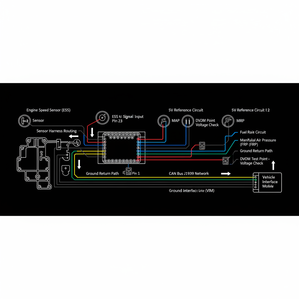
Fault Overview
Range sensor not reporting neutral/park, output speed sensor showing residual speed, incorrect PTO enable parameters, and body-builder interlock logic conflicts are the most common causes. Range sensor adjustment and residual output speed (vehicle not fully stopped) are the most frequent inhibits.
Engine & Platform Coverage
Symptoms
- •PTO will not engage transmission
- •PTO inhibit neutral
- •PTO blocked by speed
- •transmission PTO interlock
- •stationary PTO range fault
Possible Causes
- 1.Range sensor not reporting neutral/park
- 2.Output speed sensor showing residual speed
- 3.Incorrect PTO enable parameters
- 4.Wiring or switch faults on the range or speed circuits
- 5.Body-builder interlock logic conflicts
Wiring & Circuit Notes
Range sensor, output speed sensor, and any dedicated PTO enable circuits between transmission, engine, and body controller.
DVOM Specs & Sensor Tests
Range status and output speed while attempting PTO engagement. PTO enable request and inhibit reason PIDs. Parameter settings for allowable range and maximum speed.
Diagnostic Flow — FSM Sequence
AI Diesel Tech enforces this evidence-gate sequence. Each gate must pass before advancing.
6 steps locked behind Technician Mode- 1Step 1 — Confirm the Vehicle Is in the Required Range and Fully Stopped: Verify the vehicle is in the required range (usually neutral or park) and fully stopped before attempting PTO engagement.
- 2Step 2 — Monitor Range and Output Speed Data During the Engagement Attempt: Monitor range position and output speed data while attempting PTO engagement. Identify which condition is not being met.
- 3Step 3 — Check for Any Active Inhibit Messages: Check for active PTO inhibit messages in the TCM, body controller, or PTO controller.
- 4Step 4 — Verify Range Sensor Adjustment and Circuit: Verify range sensor adjustment and circuit integrity if the range is not being reported correctly.
- 5Step 5 — Review PTO Enable Parameters in the TCM and Body Controller: Review PTO enable parameters — allowable range, maximum speed, and any additional conditions — in both the TCM and body controller.
- 6Step 6 — Inspect Body-Builder Interlocks: Inspect body-builder interlock wiring and logic for any additional conditions not obvious from the chassis wiring.
- 7Step 7 — Correct the Inhibiting Condition and Retest Engagement: Correct the specific inhibiting condition and retest PTO engagement.
Unlock the full evidence-gated diagnostic sequence, DVOM test steps, and repair procedures in Technician Mode.
Full Diagnostic Access
Verification steps, preventative measures, severity guidance, and legacy comparison are available in Technician Mode.
Typical Repair Costs
Adjust or replace range sensor $100–350; correct speed sensor faults $100–300; adjust parameters $50–150; repair body-builder wiring or logic $50–400.
Start Diagnosing This Fault Now
AI Diesel Tech walks you through every evidence gate in the correct order. Choose the plan that fits your shop.
AI Diesel Tech — The Technician's Diagnostic Engine
AI Diesel Tech diagnostic logic is built by an ASE Certified Diesel Technician and engineered for professional shop use. Trusted by technicians nationwide — used in shops, fleets, and training programs.
Summary
Use the AI Diesel Tech diagnostic engine to run this code through a structured, evidence-gated sequence and get a confirmed root cause before any parts are replaced.