
Multiple Sensor Codes at Once: Shared 5V Isolation Drill
When many sensors fail together, isolate the shared supply before replacing parts. Technicians replacing many sensors and still missing the one shorted device or harness pinch is the most documented pattern. The FSM turns a confusing multi-code event into a linear isolation drill.
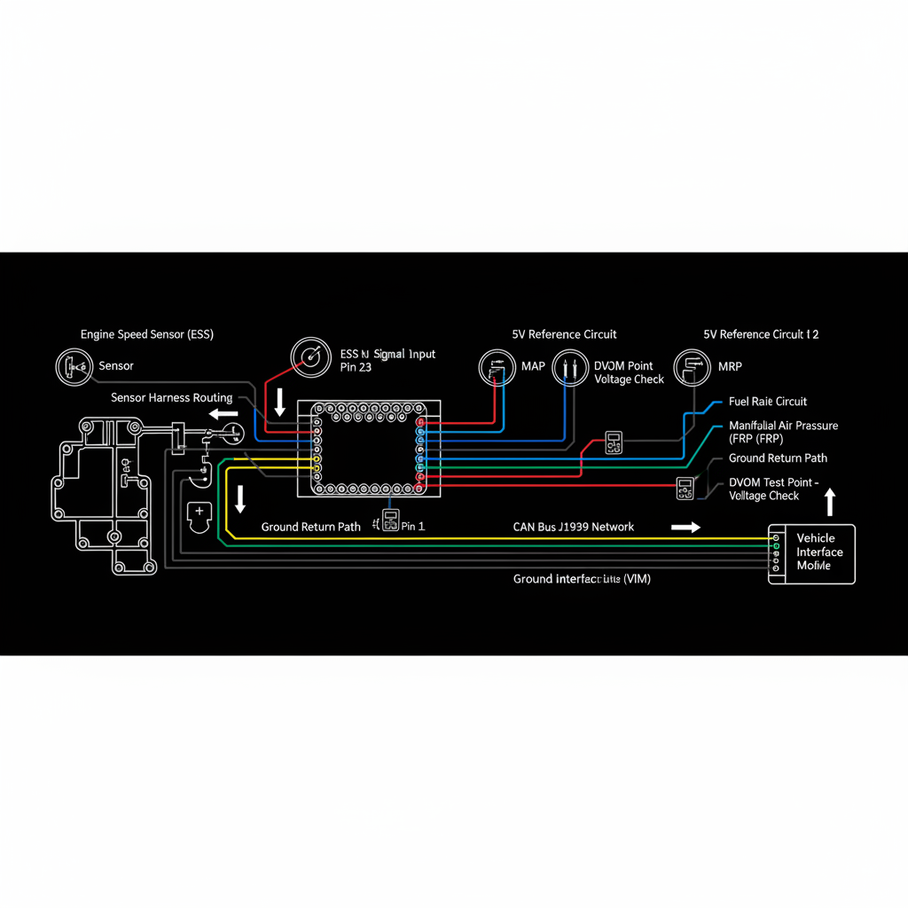
Fault Overview
Multiple sensor codes at once is a process page for cascades of sensor circuit codes caused by one failed reference supply or one shorted sensor on a shared bus. One shorted sensor, harness short to ground or power, water intrusion, and failed ECM supply (less common) are the primary causes. Technicians replacing many sensors and still missing the one shorted device or harness pinch is a documented pattern. Replacing multiple sensors without measuring the reference voltage first is the most documented misdiagnosis pattern.
Engine & Platform Coverage
Symptoms
- •Multiple sensor codes at once
- •5V reference short
- •All sensors failed diesel
- •Isolate shorted sensor bus
- •Cascade of sensor codes from one shorted device
Possible Causes
- 1.One shorted sensor — one shorted sensor pulling down the shared reference supply
- 2.Harness short to ground or power — harness short producing reference voltage fault
- 3.Water intrusion — water intrusion producing short circuit on reference bus
- 4.Failed ECM supply — failed ECM supply driver producing below-normal reference (less common)
Diagnostic Flow — FSM Sequence
AI Diesel Tech enforces this evidence-gate sequence. Each gate must pass before advancing.
4 steps locked behind Technician Mode- 1Step 1 — List All Simultaneous Codes: List all simultaneous sensor codes. Identify which sensors are reporting faults simultaneously. Simultaneous sensor faults on multiple sensors suggest a shared reference supply fault rather than individual sensor failures. Identify which reference supply bank the affected sensors share.
- 2Step 2 — Measure Vref: Measure reference voltage key-on engine-off. A significantly low reference voltage under key-on indicates bus loading or a short. A reference voltage near zero with multiple sensor codes confirms a shared supply fault. Confirm the reference voltage is below specification before proceeding.
- 3Step 3 — Disconnect Isolation: Disconnect sensors and branches one group at a time until voltage recovers. Any sensor on the shared reference can pull the bus down. Use isolation by disconnect groups. The branch that restores reference voltage when disconnected contains the fault. Inspect for recent service disturbances that may have pinched or damaged the harness.
- 4Step 4 — Repair Offender: Repair the offender within the identified branch. Disconnect individual sensors within the identified branch until the shorted device is isolated. Replace the shorted sensor or repair the harness section as required.
- 5Step 5 — Confirm Vref and Code Cleanup: Confirm reference voltage returns to specification and all related codes clear after repair. Verify reference voltage is within specification after repair. Confirm all cascade sensor codes clear after repair. A code that does not clear after repair confirms an additional fault or incomplete repair.
Unlock the full evidence-gated diagnostic sequence, DVOM test steps, and repair procedures in Technician Mode.
Repair Steps
2 steps locked- 1Replace shorted sensor if sensor failure is confirmed.
- 2Repair harness section if harness short is confirmed.
- 3Service connector if water intrusion is confirmed.
- 4Replace ECM only if supply remains dead with all loads removed and power and grounds are perfect.
Unlock full diagnostic steps, DVOM tests, and repair procedures.
Full Diagnostic Access
Verification steps, preventative measures, severity guidance, and legacy comparison are available in Technician Mode.
Start Diagnosing This Fault Now
AI Diesel Tech walks you through every evidence gate in the correct order. Choose the plan that fits your shop.
Related Resources
Related Fault Codes
AI Diesel Tech — The Technician's Diagnostic Engine
AI Diesel Tech diagnostic logic is built by an ASE Certified Diesel Technician and engineered for professional shop use. Trusted by technicians nationwide — used in shops, fleets, and training programs.
Summary
When many sensors fail together, isolate the shared supply before replacing parts. The AI Diesel Tech FSM turns a confusing multi-code event into a linear isolation drill.