
Glow Plug Control Module Supply / Enable Circuit Open Class
GPCM supply or enable open is a power delivery problem until proven otherwise. Verify voltage and ground at the module before replacement.
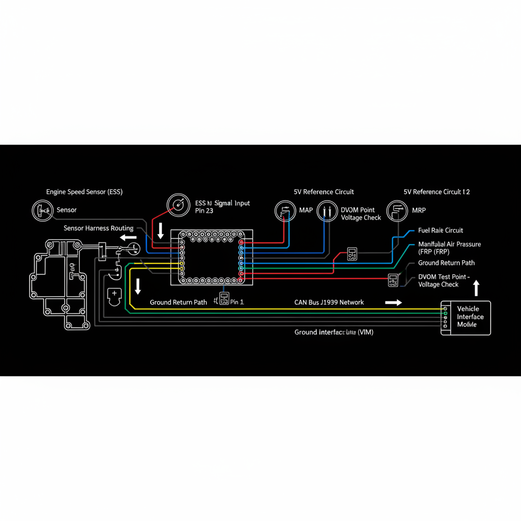
Fault Overview
This page covers open-circuit faults on the glow plug control module (GPCM) battery supply or enable/control input. The ECM or GPCM detects missing power or enable signal when glow strategy is active. Without proper power and enable, the GPCM cannot operate the glow plugs regardless of its internal condition.
Engine & Platform Coverage
Symptoms
- •Glow plug module no power condition
- •GPCM enable circuit open
- •Glow plugs not working
- •Hard start in cold weather
- •Wait-to-start lamp normal but no glow plug heat
Possible Causes
- 1.Open fuse or fusible link to GPCM
- 2.Open battery feed cable
- 3.Open enable wire from ECM
- 4.Failed GPCM internal power circuit
- 5.Corroded power connector
Diagnostic Flow — FSM Sequence
AI Diesel Tech enforces this evidence-gate sequence. Each gate must pass before advancing.
5 steps locked behind Technician Mode- 1Step 1 — Check All Related Fuses: Inspect all fuses in the GPCM power and control circuits. A blown fuse is the most common and least expensive cause of a GPCM power open. Check both the high-current power fuse and any control-side fuses.
- 2Step 2 — Measure Battery Voltage at GPCM Power Pins: Measure battery voltage at the GPCM power input pins key-on. Voltage must be present and within 0.5 V of battery voltage. Absent or low voltage confirms an open or high-resistance in the power feed.
- 3Step 3 — Verify Ground Integrity with Voltage Drop: Measure voltage drop from the GPCM ground pin to battery negative under load. Drop should be below 0.1 V. Excessive drop indicates a poor ground connection.
- 4Step 4 — Check Enable Signal from ECM During Glow Cycle: Monitor the enable signal from the ECM to the GPCM during a cold-start glow cycle. The enable signal must be present and correct for the GPCM to activate the glow plugs.
- 5Step 5 — Inspect Connectors for Corrosion: Inspect all GPCM connectors for corrosion, water intrusion, and backed-out pins. Corroded power connectors are a documented cause of GPCM power faults on multiple platforms.
- 6Step 6 — Consider GPCM Replacement: Only after power, ground, and enable are all proven correct, consider GPCM replacement for an internal power circuit failure.
Unlock the full evidence-gated diagnostic sequence, DVOM test steps, and repair procedures in Technician Mode.
Repair Steps
3 steps locked- 1Replace blown fuse and identify root cause of overcurrent.
- 2Repair open power feed wire or cable.
- 3Repair open enable wire from ECM.
- 4Clean or replace corroded GPCM connector.
- 5Replace GPCM only after power and enable are confirmed correct.
Unlock full diagnostic steps, DVOM tests, and repair procedures.
Full Diagnostic Access
Verification steps, preventative measures, severity guidance, and legacy comparison are available in Technician Mode.
Start Diagnosing This Fault Now
AI Diesel Tech walks you through every evidence gate in the correct order. Choose the plan that fits your shop.
Related Resources
Related Fault Codes
Related Systems
Related Fault Codes
Related Sensor Locations
Common Symptoms
Related Articles
AI Diesel Tech — The Technician's Diagnostic Engine
AI Diesel Tech diagnostic logic is built by an ASE Certified Diesel Technician and engineered for professional shop use. Trusted by technicians nationwide — used in shops, fleets, and training programs.
Summary
GPCM supply or enable open is a power delivery problem until proven otherwise. Verify voltage and ground at the module before replacement.