
Engine Speed vs Transmission Input Speed Correlation Fault
A rationality fault where engine crankshaft speed and transmission input (turbine) speed differ beyond calibrated limits during lock-up or direct drive. Prove both sensor circuits electrically before diagnosing converter clutch or mechanical transmission problems.
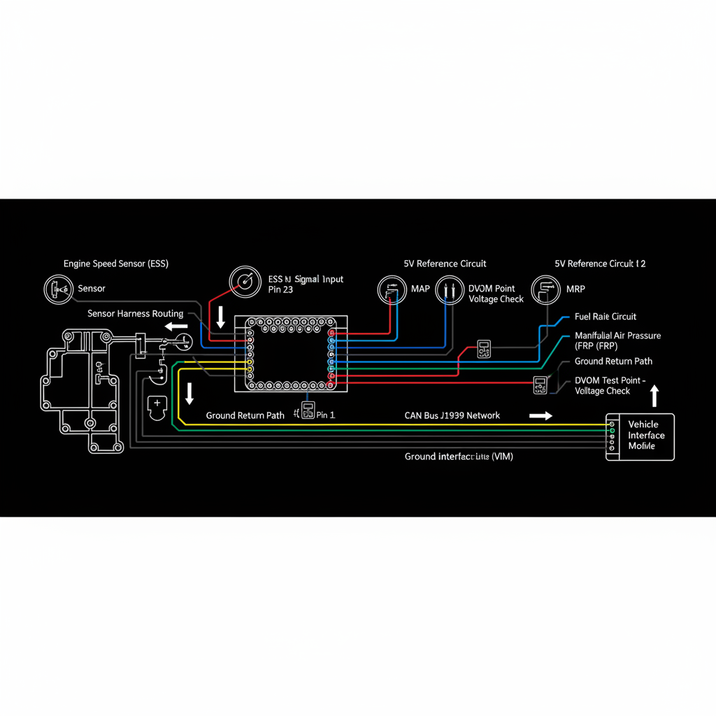
Fault Overview
True converter clutch failure produces a consistent speed difference under load. Sensor or wiring faults produce intermittent or condition-specific mismatches. Always confirm both sensors before condemning the converter. Persistent correlation faults often force limp mode or inhibit lock-up, raising transmission temperatures.
Engine & Platform Coverage
Symptoms
- •engine vs turbine speed correlation
- •speed mismatch
- •ISS vs engine speed
- •converter slip code
- •input speed rationality
Possible Causes
- 1.Actual converter clutch slip or failure
- 2.Incorrect engine or input speed sensor readings
- 3.Wiring or sensor faults on either circuit
- 4.Programming mismatch after module replacement
- 5.Mechanical transmission problems (clutch pack slip)
Wiring & Circuit Notes
Verify both engine speed (CKP) and transmission input speed sensor circuits are free of intermittents and voltage issues. Scope patterns if available.
DVOM Specs & Sensor Tests
Live comparison of engine RPM and transmission input speed during lock-up or in gears where ratio should be 1:1. Sensor air gaps and tone-wheel condition on both ends.
Diagnostic Flow — FSM Sequence
AI Diesel Tech enforces this evidence-gate sequence. Each gate must pass before advancing.
5 steps locked behind Technician Mode- 1Step 1 — Monitor Engine Speed and Input Speed Simultaneously During Lock-Up and Under Load: Record both engine RPM and transmission input speed during converter lock-up and under steady load. Note the magnitude and conditions of any difference.
- 2Step 2 — Note the Conditions Where the Difference Appears: Determine whether the mismatch is constant, load-dependent, or intermittent. Constant mismatch under load suggests mechanical slip; intermittent suggests sensor or wiring.
- 3Step 3 — Verify Both Sensor Circuits Electrically: Check both the engine speed (CKP) and transmission input speed sensor circuits for opens, shorts, and connector integrity.
- 4Step 4 — Check Tone Wheels and Air Gaps on Both Sensors: Inspect tone wheels and measure air gaps on both the crankshaft position sensor and the transmission input speed sensor.
- 5Step 5 — Evaluate Converter Clutch Apply Data and Pressure if Available: Review converter clutch command status, apply pressure, and solenoid operation. Confirm the clutch is being commanded on during the test.
- 6Step 6 — Repair Sensor/Wiring Issues First; Then Diagnose Mechanical Converter or Clutch Problems: Correct any electrical faults first. Only proceed to converter or internal transmission diagnosis after both sensor circuits are proven.
Unlock the full evidence-gated diagnostic sequence, DVOM test steps, and repair procedures in Technician Mode.
Full Diagnostic Access
Verification steps, preventative measures, severity guidance, and legacy comparison are available in Technician Mode.
Typical Repair Costs
Repair speed sensor circuits $100–300; correct air gaps $50–150; address converter clutch hydraulic or mechanical faults $500–2,500+.
Start Diagnosing This Fault Now
AI Diesel Tech walks you through every evidence gate in the correct order. Choose the plan that fits your shop.
AI Diesel Tech — The Technician's Diagnostic Engine
AI Diesel Tech diagnostic logic is built by an ASE Certified Diesel Technician and engineered for professional shop use. Trusted by technicians nationwide — used in shops, fleets, and training programs.
Summary
Use the AI Diesel Tech diagnostic engine to run this code through a structured, evidence-gated sequence and get a confirmed root cause before any parts are replaced.