
System — Diesel Powertrain Speed Source Arbitration Standard
Most speed conflicts are resolved by correcting a single biased sensor or a tire-size mismatch rather than replacing multiple components. This standard applies to every speed-related complaint on an integrated diesel powertrain.
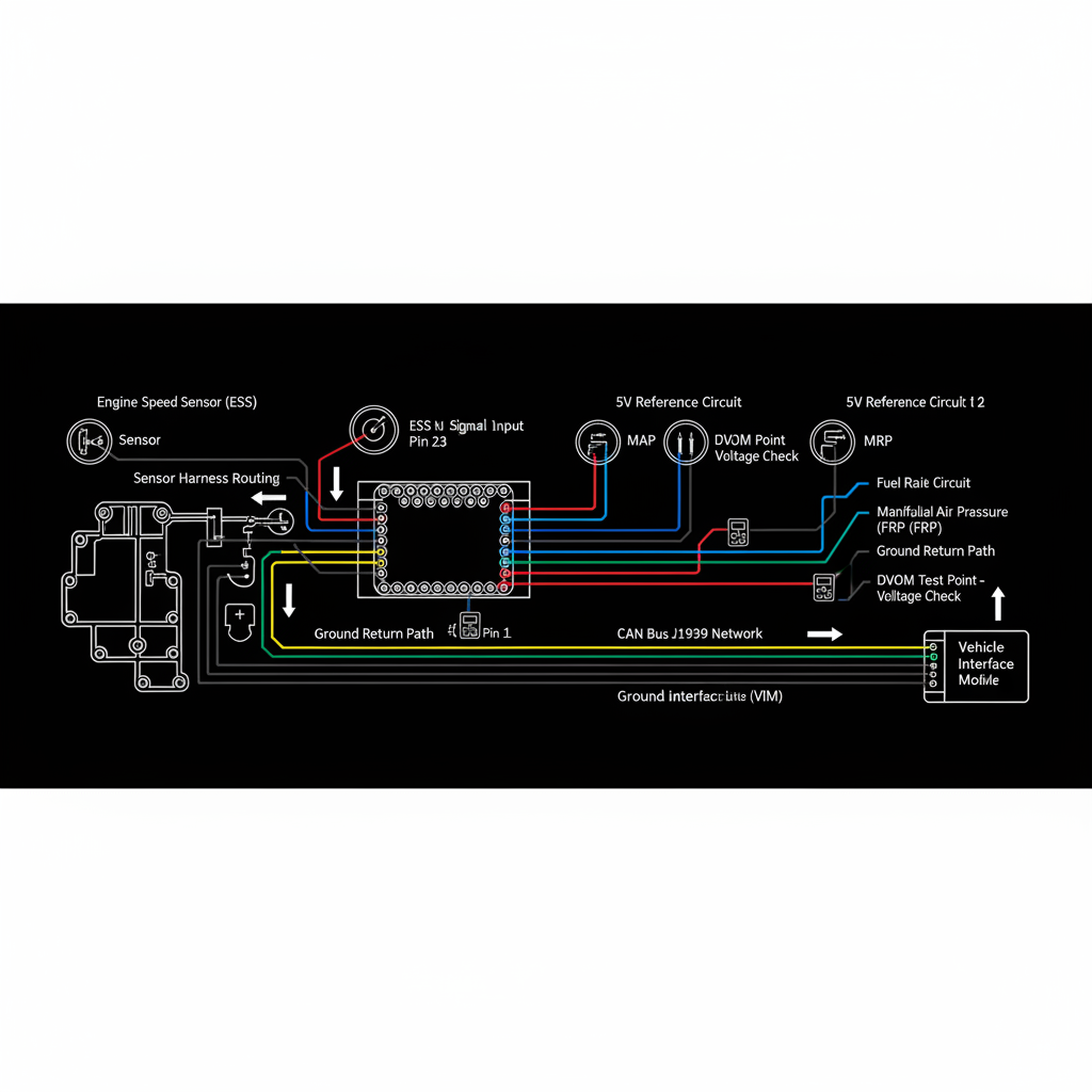
Fault Overview
System standard for evaluating and correcting conflicts among engine speed, transmission input/output speed, ABS wheel speeds, and any other broadcast speed sources. Applying this standard on every speed-related complaint reduces diagnostic time and parts cost.
Engine & Platform Coverage
Symptoms
- •speed source arbitration
- •multiple speed sources
- •speed conflict resolution
- •powertrain speed standard
Possible Causes
- 1.Single biased speed sensor
- 2.Tire size or axle ratio programming mismatch
- 3.Damaged tone wheel on one source
- 4.Network message loss
- 5.Aftermarket device interference
Wiring & Circuit Notes
Each individual speed sensor circuit and the J1939 network that carries the broadcast values.
DVOM Specs & Sensor Tests
Simultaneous live data from every available speed source at a known vehicle speed. Parameter settings for tire size and axle ratio in every module. Network message validity.
Diagnostic Flow — FSM Sequence
AI Diesel Tech enforces this evidence-gate sequence. Each gate must pass before advancing.
6 steps locked behind Technician Mode- 1Step 1 — Record All Speed Sources at a Constant, Known Road Speed: Record engine speed, transmission input/output speed, and all ABS wheel speeds simultaneously at a constant, known road speed.
- 2Step 2 — Identify Any Source That Disagrees by More Than a Few Percent: Identify the single source that differs from the others by more than a few percent. This is the outlier.
- 3Step 3 — Verify Tire Size and Axle Ratio Programming in ECM, TCM, and ABS: Verify tire size and axle ratio programming in every module. A mismatch is the most common cause of persistent speed conflicts.
- 4Step 4 — Inspect the Physical Sensor and Tone Wheel of the Outlier: Inspect the sensor and tone wheel associated with the outlier for damage, incorrect air gap, or debris.
- 5Step 5 — Check Wiring and Air Gap: Check wiring and air gap for the outlier sensor.
- 6Step 6 — Correct the Single Biased Source or the Programming Error: Correct the single biased source or the programming error. Do not replace multiple sensors.
- 7Step 7 — Confirm All Sources Now Agree: Verify all speed sources agree at a known road speed after the correction.
Unlock the full evidence-gated diagnostic sequence, DVOM test steps, and repair procedures in Technician Mode.
Full Diagnostic Access
Verification steps, preventative measures, severity guidance, and legacy comparison are available in Technician Mode.
Typical Repair Costs
Correct programming $50–150; replace or adjust the single failed sensor $100–300; repair wiring or tone wheel $80–400.
Start Diagnosing This Fault Now
AI Diesel Tech walks you through every evidence gate in the correct order. Choose the plan that fits your shop.
AI Diesel Tech — The Technician's Diagnostic Engine
AI Diesel Tech diagnostic logic is built by an ASE Certified Diesel Technician and engineered for professional shop use. Trusted by technicians nationwide — used in shops, fleets, and training programs.
Summary
Use the AI Diesel Tech diagnostic engine to run this code through a structured, evidence-gated sequence and get a confirmed root cause before any parts are replaced.