
Cruise Control Inhibit Input Circuit Voltage Above / Below Normal
Cruise inhibit voltage faults are almost always a switch, adjustment, or simple wiring issue. Identify the specific input first.
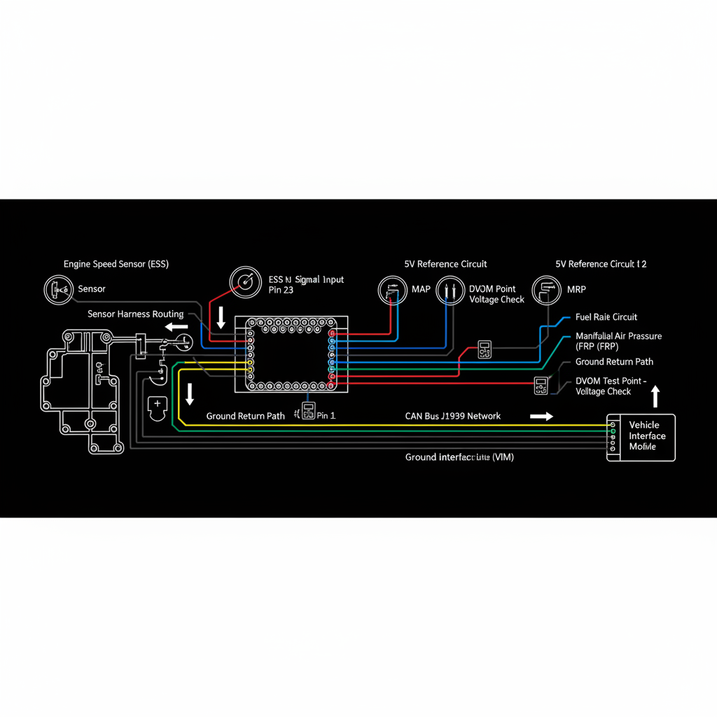
Fault Overview
Covers voltage faults on the cruise control inhibit inputs (brake, clutch, neutral, or dedicated inhibit circuits). High or low voltage indicates a circuit fault that prevents cruise engagement or causes dropout.
Engine & Platform Coverage
Symptoms
- •Cruise inhibit fault
- •Cruise won't set — brake switch
- •Clutch switch cruise fault
- •Neutral switch cruise inhibit
- •Cruise control circuit voltage fault
Possible Causes
- 1.Faulty brake lamp switch or cruise cancel switch
- 2.Clutch switch misadjusted or failed
- 3.Neutral safety switch issues
- 4.Wiring short or open on inhibit circuits
- 5.Incorrect switch installation after clutch or transmission work
Diagnostic Flow — FSM Sequence
AI Diesel Tech enforces this evidence-gate sequence. Each gate must pass before advancing.
5 steps locked behind Technician Mode- 1Step 1 — Identify Which Inhibit Input Is Flagged: Use scan tool to identify which specific inhibit input is reporting the fault. Brake, clutch, and neutral inhibits have different root causes and repair paths.
- 2Step 2 — Monitor Switch Status vs Actual Pedal or Lever Position: Monitor the flagged switch status in live data while operating the pedal or lever. The reported state must match the actual physical position.
- 3Step 3 — Measure Voltage on Signal Circuit in Both States: Measure voltage on the signal circuit in both the activated and released positions. Compare to expected values for the switch type.
- 4Step 4 — Check Mechanical Adjustment: Check mechanical adjustment of clutch or neutral switches. Adjustment is required after almost every clutch replacement and is a leading cause of inhibit faults.
- 5Step 5 — Inspect Wiring for Shorts or Opens: Inspect the inhibit circuit wiring for shorts or opens, especially near the pedal and at intermediate connectors.
- 6Step 6 — Verify No Aftermarket Devices Are Pulling the Circuit: Verify no aftermarket trailer brake controllers or other devices are interfering with the inhibit circuit.
Unlock the full evidence-gated diagnostic sequence, DVOM test steps, and repair procedures in Technician Mode.
Repair Steps
1 steps locked- 1Replace or adjust brake/clutch/neutral switch.
- 2Repair wiring.
- 3Correct aftermarket interference.
Unlock full diagnostic steps, DVOM tests, and repair procedures.
Full Diagnostic Access
Verification steps, preventative measures, severity guidance, and legacy comparison are available in Technician Mode.
Start Diagnosing This Fault Now
AI Diesel Tech walks you through every evidence gate in the correct order. Choose the plan that fits your shop.
Related Resources
Related Fault Codes
Related Systems
Related Fault Codes
Related Sensor Locations
Common Symptoms
Related Articles
AI Diesel Tech — The Technician's Diagnostic Engine
AI Diesel Tech diagnostic logic is built by an ASE Certified Diesel Technician and engineered for professional shop use. Trusted by technicians nationwide — used in shops, fleets, and training programs.
Summary
Cruise inhibit voltage faults are almost always a switch, adjustment, or simple wiring issue. Identify the specific input first.