
Cold Start Aid Heater Relay Feedback / Status Conflict
Command vs feedback conflict on the heater relay is resolved by measuring both sides and proving relay operation under load.
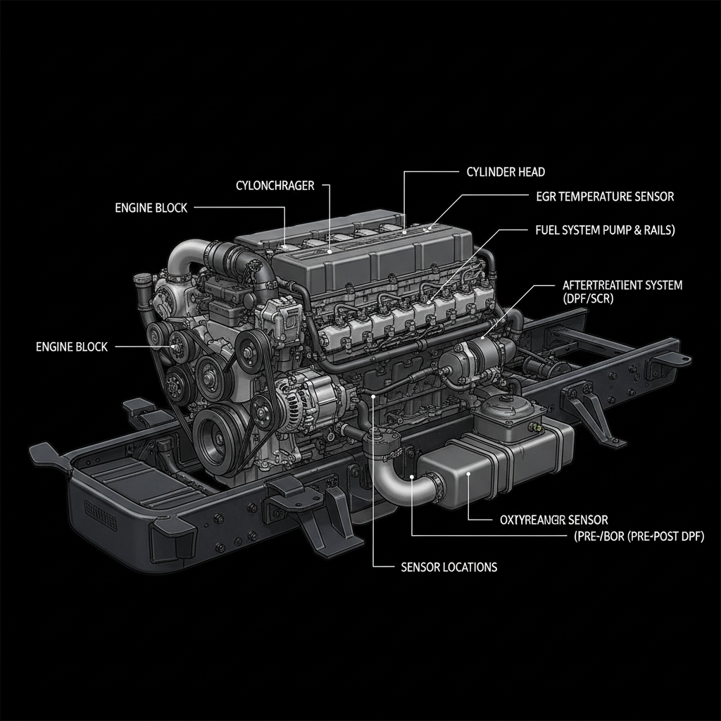
Fault Overview
Conflict between commanded state of the cold start aid relay and the feedback or status signal returned to the ECM. Indicates the relay is not achieving or reporting the expected state. This fault class covers monitoring systems that compare command to feedback rather than simple circuit voltage or current checks.
Engine & Platform Coverage
Symptoms
- •Heater relay feedback fault active
- •Status conflict on cold start aid
- •Relay command vs status mismatch
Possible Causes
- 1.Failed relay contacts
- 2.Feedback wire open or shorted
- 3.Incorrect relay installed
- 4.Voltage drop affecting feedback logic
- 5.ECM input fault
Diagnostic Flow — FSM Sequence
AI Diesel Tech enforces this evidence-gate sequence. Each gate must pass before advancing.
4 steps locked behind Technician Mode- 1Step 1 — Monitor Command and Feedback/Status Simultaneously: Use scan tool to monitor heater command and feedback/status simultaneously during a cold-start cycle. Document the exact conditions under which the conflict occurs.
- 2Step 2 — Measure Load-Side Voltage When Commanded On: Measure voltage at the relay load side when the relay is commanded on. Voltage present confirms the relay is switching; absent confirms relay contact failure.
- 3Step 3 — Check Feedback Circuit Voltage and Continuity: Measure voltage on the feedback circuit in both commanded states. Perform continuity test on the feedback wire. An open or shorted feedback wire will cause a conflict even when the relay is operating correctly.
- 4Step 4 — Substitute Known-Good Relay: Substitute a known-good relay of the identical part number and retest. Relay contact degradation after high-current cycling is the most common cause of command/feedback mismatches.
- 5Step 5 — Verify Wiring Integrity: Inspect all relay socket, control, load, and feedback circuit wiring for damage, corrosion, or incorrect connections.
Unlock the full evidence-gated diagnostic sequence, DVOM test steps, and repair procedures in Technician Mode.
Repair Steps
2 steps locked- 1Replace relay with degraded contacts.
- 2Repair open or shorted feedback wire.
- 3Correct any voltage supply issues affecting feedback logic.
- 4Repair ECM input circuit only after relay and wiring are proven good.
Unlock full diagnostic steps, DVOM tests, and repair procedures.
Full Diagnostic Access
Verification steps, preventative measures, severity guidance, and legacy comparison are available in Technician Mode.
Start Diagnosing This Fault Now
AI Diesel Tech walks you through every evidence gate in the correct order. Choose the plan that fits your shop.
Related Resources
Related Fault Codes
AI Diesel Tech — The Technician's Diagnostic Engine
AI Diesel Tech diagnostic logic is built by an ASE Certified Diesel Technician and engineered for professional shop use. Trusted by technicians nationwide — used in shops, fleets, and training programs.
Summary
Command vs feedback conflict on the heater relay is resolved by measuring both sides and proving relay operation under load.